Máy hiện sóng, Oscilloscope LeCroy HDO6104 1 GHz, 4 CH
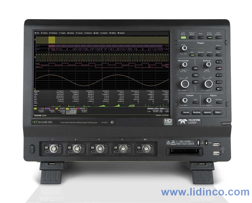
Máy hiện sóng, Oscilloscope LeCroy HDO6104 1 GHz, 4 CH
- Đang có sẵn: Vui lòng liên hệ
- Tạm thời chưa có khuyến mãi cho sản phẩm này
Hotline: 0906.988.447
Liên hệ: Hồ Chí Minh
- Điện thoại: (028).3977.8269
- Email: [email protected]
- Địa chỉ: 487 Cộng Hòa, Phường Tân Bình, TP. Hồ Chí Minh, Việt Nam
Liên hệ: Bắc Ninh, Hà Nội
- Điện thoại: (0222).730.0180
- Email: [email protected]
- Địa chỉ: 184 Bình Than, Phường Võ Cường, Bắc Ninh, Việt Nam
-
 Tư vấn kĩ thuật
Miễn phí
Tư vấn kĩ thuật
Miễn phí
-
 Miễn phí vận chuyển
Đơn hàng trên 3 triệu
Miễn phí vận chuyển
Đơn hàng trên 3 triệu
Băng thông: 1 GHz
Số kênh: 4 kênh analog
Tốc độ lấy mẫu: 10 GS/s
Độ dài bản ghi sóng: 50 Mpts / 250 Mpts
Độ nhạy: 1 MΩ: 1 mV / div – 10 V / div, biến đầy đủ;
50 Ω: 1 mV / div – 1 V / div, biến đầy đủ
Suy hao: ±(0.5%) F.S, offset at 0 V
Độ phân giải dọc:Độ phân giải ADC 12 bit, lên đến 15 bit với độ phân giải nâng cao
Input/Output: DC, AC, GND
Kiểu Trigger: Normal, Auto, Single
Nguồn Trigger: AC, DC, LFRJ, HFRJ, Noise RJ (CH1 ~ CH4)
Kiểu Trigger: Edge, Slope, Pulse Width, Window, Runt, Interval, Time Out (Dropout), Pattern and Video.
Chức năng toán học:Độ lớn quang phổ. Đặt Thang đo dọc FFT thành RMS tuyến tính hoặc dBV RMS và Cửa sổ FFT thành Hình chữ nhật, Hamming, Hanning hoặc Blackman-Harris.
Xử lý và phân tích dữ liệu: Tìm kiếm, điều hướng, lịch sử, mask test, giản đồ Bode, phân tích năng lượng (tùy chọn) và đếm
Giao tiếp: USB Host, USB Device, LAN, GPIB
Hệ điều hành: Intel® i3-6100 Dual Core, 3.7 GHz (or better)
Hiển thị: Màn hình cảm ứng đa điểm TFT-LCD rộng 12,1 ”
Kích thước: 352 mm * 128 mm * 224 mm
Trọng lượng: N.W 3.4 Kg (2-ch); 3.6 Kg (4-ch)
G.W 4.9 Kg (2-ch); 5.2 Kg (4-ch)
Giới thiệu
Máy hiện sóng LeCroy DHO6104 băng thông 1 GHz, lấy mẫu 2.5 GSa/s, 4 kênh, bộ nhớ 50 Mpts/kênh, màn hình cảm ứng 12.1 inch.

- 12-bit ADC resolution, up to 15 bits with enhanced resolution
- 350 MHz, 500 MHz and 1 GHz bandwidths
- Long Memory – up to 250 Mpts/Ch
- 12.1” toucn screen display
- Spectrum Analyzer Mode
- WaveScan – Advanced Search and Find
- History Mode – Waveform Playback
- Power Analysis Software
- JITKIT Clock-Data Jitter Analysis
- Serial Data Trigger and Decode
- PROTObus MAG Serial Data Debug Toolkit
- LabNotebook Report Generation
- Advanced Trigger Tools including TriggerScan and Software Assisted Trigger
- 16 Digital Channels with 1.25 GS/s Sample Rate
- Mixed Signal Debug Capabilities
- Analog and Digital Cross Pattern Triggering
- Digital Pattern Search and Find
- Analog and Digital Timing Measurements
- Logic Gate Emulation
HD4096 high definition technology enables oscilloscopes to capture and display signals of up to 1 GHz with high sample rate and 16 times more resolution than other oscilloscopes.
![]()
Waveforms captured and displayed on oscilloscopes with HD4096 technology are cleaner and crisper. Signal details often lost in the noise are clearly visible and easy to distinguish HD4096 enables oscilloscopes to deliver unmatched measurement precision for improved debug and analysis.
Comprehensive set of waveform math and measurement tools extends the debugging and analysis capability.
Complete set of solutions available for embedded, digital, power and automotive designs extends analysis
View signal details in the frequency domain with a spectrum analyzer style user interface
Quickly locate analog or digital waveforms for runts, glitches or other anomolies with WaveScan
Scroll back in time to isolate anomalies and quickly find the source of the problem.
![]()
Easily control channels, trigger, math and measurements with the large multi-touch display and intuitive interface.
PROTObus MAG Toolkit extends serial data trigger and decode functions with integrated parameter measurements
Measure and analyze operating characteristics of power conversion devices and circuits
Capture many fast pulses separated by long delays in quick succession while maintaining fast sampling
View decoded protocol information on top of physical layer waveforms and trigger on protocol specific messages
Save all results and data with a single button press and create custom reports with LabNotebook
Flexible analog and digital cross-pattern triggering across all 20 channels
Perform timing measurements on digital signals and analyze with trends, statistics and histicons
Find a digital pattern across many digital lines using the parallel pattern search capability of WaveScan
Quickly see the state of all the digital lines at the same time using convenient activity indicators.
Simulate complete digital designs using logic gate emulation.
Vertical System | |
| Bandwidth | 1 GHz |
| Analog Bandwidth (Max) | 1 GHz |
| Analog Bandwidth @ 50 Ω (-3 dB) (ProBus Input) | 1 GHz (≥1 mV/div) |
| Analog Bandwidth @ 1 MΩ (-3 dB) (ProBus Input) | 500 MHz (typical) |
| Rise Time (10-90%, 50 Ω) | 450 ps (typical) |
| Input Channels | 4 |
| Bandwidth Limiters | 20MHz, 200MHz |
| Input Impedance | 1 MΩ ± 2.0% || 15 pF, 50 Ω ± 2.0% |
| Input Coupling | 1 MΩ: AC, DC, GND; 50 Ω: DC, GND |
| Maximum Input Voltage | 50 Ω: 5 Vrms, 1 MΩ: 400 V max (DC + Peak AC ≤ 10 kHz) |
| Channel-Channel Isolation | DC-400MHz > 1000:1; 400MHz up to rated BW > 300:1 |
| Vertical Resolution | 12 bits; up to 15 bits with enhanced resolution (ERES) |
| Sensitivity | 50 Ω: 1 mV-1 V/div, fully variable; 1 MΩ: 1 mV-10 V/div, fully variable |
| DC Gain Accuracy | ±(0.5%) F.S, offset at 0 V |
| DC Vertical Gain Accuracy (Gain Component of DC Accuracy) | ±(0.5%) F.S, offset at 0 V |
| Offset Range | 50 Ω ±1.6 V @ 1 mV - 4.95 mV/div ±4 V @ 5 mV - 9.9 mV/div ±8 V @ 10 mV - 19.8 mV/div ±10 V @ 20 mV - 1 V/div1 MΩ ±1.6 V @ 1 mV - 4.95 mV/div ±4 V @ 5 mV - 9.9 mV/div ±8 V @ 10 mV - 19.8 mV/div ±16 V @ 20 mV - 100 mV/div ±80 V @ 102 mV - 198 mV/div ±160 V @ 200 mV - 1 V/div ±400 V @ 1.02 V - 10 V/div |
| Offset Accuracy | +/-(1.0% of offset setting + 0.5%FS + 0.02% of max offset + 1mV) |
| DC Vertical Offset Accuracy | ±(1.0% of offset setting + 0.5%FS + 0.02% of max offset + 1mV) |
Horizontal System | |
| Timebases | Internal timebase common to 4 input channels; an external clock may be applied at the auxiliary input |
| Time/Division Range | 20 ps/div - 5 ks/div with standard memory (up to 10 ks/div with -L memory, 25 ks/div with -XL memory); RIS available at ≤ 10 ns/div; Roll Mode available at ≥ 100 ms/div and ≤ 5 MS/s |
| Clock Accuracy | +/-2.5ppm + 1.0ppm/year from calibration |
| Jitter Noise Floor | 700fs |
| Trigger and Interpolator Jitter | ≤ 4 ps RMS (typical) <0.1 ps RMS (typical, software assisted) |
| Channel-Channel Deskew Range | ±9 x time/div. setting, 100 ms max., each channel |
| External Timebase Reference (Input) | 10MHz +/-25ppm at 0 to 10dBm into 50Ohms |
| External Timebase Reference (Output) | 10MHz, 3.5 dBm +/-1dBm, syncronized to reference being used (internal or external reference) via LBUS BNC adaptor |
| External Clock | DC to 100 MHz; (50 Ω/1 MΩ), EXT BNC input, Minimum rise time and amplitude requirements apply at low frequencies. |
Acquisition System | |
| Single-Shot Sample Rate/Ch | 2.5 GS/s on 4 Ch |
| Random Interleaved Sampling (RIS) | 125 GS/s for repetitive signals (20 ps/div to 10 ns/div) |
| Maximum Trigger Rate | 1,000,000 waveforms/second (in Sequence Mode, up to 4 channels) |
| Intersegment Time | 1 µs |
| Maximum Acquisition Memory | 250 Mpts (4 Ch operation) |
| Standard Memory (4 Ch / 2 Ch / 1Ch) (Number of Segments) | 50M / 50M / 50M (30,000) |
| Memory Options (4 Ch / 2 Ch / 1Ch) (Number of Segments) | L- Option: 100M / 100M / 100M (60,000) XL - Option: 250M / 250M / 250M (65,000) |
Acquisition Processing | |
| Averaging | Summed averaging to 1 million sweeps; continuous averaging to 1 million sweeps |
| Enhanced Resolution (ERES) | From 12.5 to 15 bits vertical resolution |
| Envelope (Extrema) | Envelope, floor, or roof for up to 1 million sweeps |
| Interpolation | Linear or Sin x/x |
Triggering System | |
| Modes | Normal, Auto, Single, and Stop |
| Sources | Any input channel, Ext, Ext/10, or line; slope and level unique to each source (except line trigger) |
| Coupling Mode | DC, AC, HFRej, LFRej |
| Pre-trigger Delay | 0-100% of memory size (adjustable in 1% increments of 100 ns) |
| Post-trigger Delay | 0-10,000 Divisions in real time mode, limited at slower time/div settings or in roll mode |
| Hold-off by Time or Events | From 2 ns up to 20 s or from 1 to 99,999,999 events |
| Internal Trigger Range | ±4.1 div from center (typical) |
| Trigger Sensitivity with Edge Trigger ProBus Inputs | 0.9 division: 10 MHz 1.0 divisions: 200 MHz 1.5 divisions: 500 MHz 2.0 divisions: 1 GHz |
| External Trigger Sensitivity, (Edge Trigger) | 0.9 division: 10 MHz 1.0 divisions: 200 MHz 1.5 divisions: 500 MHz 2.0 divisions: 1 GHz |
| Max. Trigger Frequency, SMART Trigger | 1GHz |
| External Trigger Input Range | Ext (±0.4 V); Ext/10 (±4 V) |
Basic Triggers | |
| Edge | Triggers when signal meets slope (positive, negative, or either) and level condition. |
| Window | Triggers when signal exits a window defined by adjustable thresholds |
| TV-Composite Video | Triggers NTSC or PAL with selectable line and field; HDTV (720p, 1080i, 1080p) with selectable frame rate (50 or 60 Hz) and Line; or CUSTOM with selectable Fields (1-8), Lines (up to 2000), Frame Rates (25, 30, 50, or 60 Hz), Interlacing (1:1, 2:1, 4:1, 8:1), or Synch Pulse Slope (Positive or Negative). |
SMART Triggers | |
| State or Edge Qualified | Triggers on any input source only if a defined state or edge occurred on another input source. Delay between sources is selectable by time or events. |
| Qualified First | In Sequence acquisition mode, triggers repeatably on event B only if a defined pattern, state, or edge (event A) is satisfied in the first segment of the acquisition. Holdoff between sources is selectable by time or events. |
| Dropout | Triggers if signal drops out for longer than selected time between 1 ns and 20 s. |
| Pattern | Logic combination (AND, NAND, OR, NOR) of 5 inputs (4 channels and external trigger input). Each source can be high, low, or don?t care. The High and Low level can be selected independently. Triggers at start or end of the pattern. |
SMART Triggers with Exclusion Technology | |
| Glitch | Triggers on positive or negative glitches with selectable widths. minimum width 1.5ns, Maximum Width: 20s |
| Width (Signal or Pattern) | Triggers on positive or negative glitches with selectable widths. minimum width 1.5ns, Maximum Width: 20s |
| Interval (Signal or Pattern) | Triggers on intervals selectable between 1 ns and 20 s. |
| Timeout (State/Edge Qualified) | Triggers on any source if a given state (or transition edge) has occurred on another source. Delay between sources is 1 ns to 20 s, or 1 to 99,999,999 events. |
| Runt | Trigger on positive or negative runts defined by two voltage limits and two time limits. Select between 1 ns and 20 ns. |
| Slew Rate | Trigger on edge rates. Select limits for dV, dt, and slope. Select edge limits between 1 ns and 20 ns. |
| Exclusion Triggering | Trigger on intermittent faults by specifying the expected behavior and triggering when that condition is not met |
Cascade (Sequence) Triggering | |
| Capability | Arm on "A" event, then Trigger on "B" event. Or Arm on "A" event, then Qualify on "B" event, and Trigger on "C" event. |
| Types | Cascade A then B: Edge, Window, Pattern (Logic) Width, Glitch, Interval, Dropout, or Measurement. Measurement can be on Stage B only. Cascade A then B then C (Measurement): Edge, Window, Pattern (Logic), Width, Glitch, Interval, Dropout, or Measurement. Measurement can be on Stage C only. Cascade A then B then C: Edge, Window, Pattern (Logic) |
| Holdoff | Holdoff between A and B or B and C is selectable by time (1ns to 20s) or number of events. Measurement trigger selection as the last stage in a Cascade precludes a holdoff setting between the prior stage and the last stage. |
Low Speed Serial Protocol Triggering (Optional) | |
| Optionally available | I2C, SPI (SPI, SSPI, SIOP), UART-RS232, CAN, LIN, FlexRay, MIL-STD-1553, USB 1.x/2.0, AudioBus |
Measurement Trigger | |
| Measurement Trigger Capability | Select from a large number of measurement parameters trigger on a measurement value with qualified limits. Can be used as only trigger or last event in a Cascade Trigger. |
Color Waveform Display | |
| Type | Color 12.1" widescreen flat panel TFT-Active Matrix with high resolution touch screen |
| Resolution | WXGA; 1280 x 800 pixels. |
| Number of traces | Display a maximum of 16 traces. Simultaneously display channel, zoom, memory and math traces. |
| Grid Styles | Auto, Single, Dual, Quad, Octal, X-Y, Single+X-Y, Dual+X-Y |
| Waveform Representation | Sample dots joined, or sample dots only |
Internal Waveform Memory | |
| Internal Waveform Memory | 4 active waveform memory traces (M1-M4) store 16 bit/point full length waveforms. Waveforms can be stored to any number of files limited only by the data storage media capacity. |
Integrated Second Display | |
| Type | Supports touch screen integration of user-supplied second display with split-grid capability. |
| Resolution | (Note: touch screen driver for second display may not be a Fujitsu driver) |
Analog Persistence Display | |
| Analog and Color-Graded Persistence | Variable saturation levels; stores each trace?s persistence data in memory |
| Persistence Types | Select analog, color, or three-dimensional |
| Trace Selection | Activate persistence on all or any combination of traces |
| Persistence Aging | Select from 500 ms to infinity |
| Sweep Display Modes | All accumulated, or all accumulated with last trace highlighted |
Processor/CPU | |
| Type | Intel Core i5, 2.5 GHz (or better) |
| Processor Memory | 8 GB standard |
| Operating System | Microsoft Windows® 7 Pro 64 bit Embedded |
| Real Time Clock | Date and time displayed with waveform in hardcopy files. SNTP support to synchronize to precision internal clocks. |
Zoom Expansion Traces | |
| Zoom Expansion Traces | Display up to 8 Zoom and 8 Math/Zoom traces |
Setup Storage | |
| Front Panel and Instrument Status | Store to the internal hard drive, over the network, or to a USB-connected peripheral device. |
Interface | |
| Remote Control | Via Windows Automation, or via LeCroy Remote Command Set |
| GPIB Port | Supports IEEE - 488.2 (External) |
| Ethernet Port | Supports 2 10/100/1000BaseT Ethernet interface (RJ45 ports) |
| USB Ports | Minimum 6 total (incl. 2 front panel) USB 2.0 ports support Windows compatible devices |
| USB Device Port | 1 USBTMC port |
| External Monitor Port | 15 pin D-Type WXGA compatible DB-15 to support customer-supplied external monitor. Includes support for extended desktop operation with WXGA resolution on second monitor. |
Auxiliary Input | |
| Signal Types | Select External Trigger or External Clock Input on the front panel |
| Coupling | 50 Ω: DC; 1 MΩ: AC, DC, GND |
| Max. Input Voltage | 50 Ω: 5 Vrms; 1 MΩ: 400 Vmax (DC + Peak AC ≤ 5 kHz) |
Auxiliary Output | |
| Signal Types | Select from control signals or Off |
| Output Signal | 500 Hz-1 MHz square wave or DC level; 50 mV-1 V into 1 MΩ |
| Control Signals | Trigger enabled, trigger out, pass/fail status, off |
| Connector Type | BNC, located on rear panel |
Automatic Setup | |
| Auto Setup | Automatically sets timebase, trigger, and sensitivity to display a wide range of repetitive signals |
| Find Vertical Scale | Automatically sets the vertical sensitivity and offset for the selected channel to display a waveform with the maximum dynamic range |
Probes | |
| Probes | Qty. (4) ÷10 Passive Probes |
| Probe System | Probus. Automatically detects and supports a variety of compatible probes |
| Scale Factors | Automatically or manually selected depending on probe used |
| Calibration Output | Default is 1kHz square wave, 1Vp-p (typical), output to probe hook. Settable from 250 Hz to 1 MHz square wave; 50 mV to 1.0V. |
Power Requirements | |
| Voltage | 100-240 VAC ±10% at 45-66 Hz; 110-120 VAC ±10% at 380-420 Hz; Automatic AC Voltage Selection; Installation Category 300 V CAT II |
| Max. Power Consumption | 350 VA |
Environmental and Safety | |
| Temperature (Operating) | +5 °C to +40 °C |
| Temperature (Non-Operating) | -20 °C to +60 °C |
| Humidity (Operating) | 5% to 80% relative humidity (non-condensing) up to +31 °C. Upper limit derates to 50% relative humidity (non-condensing) at +40 °C. |
| Humidity (Non-Operating) | 5% to 95% relative humidity (non-condensing) as tested per MIL-PRF-28800F |
| Altitude (Operating) | Up to 10,000 ft. (3048 m) at or below +25 °C |
| Altitude (Non-Operating) | Up to 40,000 ft. (12,192 m) |
| Random Vibration (Operating) | 0.31 grms 5 Hz to 500 Hz, 15 minutes in each of three orthogonal axes |
| Random Vibration (Non-Operating) | 2.4 grms 5 Hz to 500 Hz, 15 minutes in each of three orthogonal axes |
| Functional Shock | 30 g peak, half sine, 11 ms pulse, 3 shocks (positive and negative) in each of three orthogonal axes, 18 shocks total |
Physical Dimensions | |
| Dimensions (HWD) | 11.48"H x 15.72"W x 5.17"D (291.7 mm x 399.4 mm x 131.31 mm) |
| Weight | 12.9 lbs. (5.86 kg.) |
| Shipping Weight | 20.2 lbs. (9.2 kg) |
Phụ kiện
-
Băng thông:
-
Tốc độ lấy mẫu:
-
Chiều dài sóng:
-
Số kênh đo:
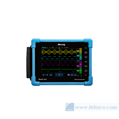
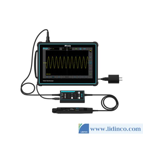
Máy hiện sóng cầm tay Micsig TO1152 150MHz

-
Tần số phát xung:
-
Tốc độ lấy mẫu:
-
Chiều dài sóng:
-
Độ phân giải dọc:
Máy phát xung Lecroy T3AFG500

-
Tần số phát xung:
-
Tốc độ lấy mẫu:
-
Chiều dài sóng:
-
Độ phân giải dọc:
Máy phát xung Lecroy T3AFG350

-
Tần số phát xung:
-
Tốc độ lấy mẫu:
-
Chiều dài sóng:
-
Độ phân giải dọc:
Máy phát xung Lecroy T3AFG200

-
Tần số phát xung:
-
Tốc độ lấy mẫu:
-
Chiều dài sóng:
-
Độ phân giải dọc:
Máy phát xung Lecroy T3AFG120

-
Tần số phát xung:
-
Tốc độ lấy mẫu:
-
Chiều dài sóng:
-
Độ phân giải dọc:
Máy phát xung Lecroy T3AFG80

-
Tần số phát xung:
-
Tốc độ lấy mẫu:
-
Chiều dài sóng:
-
Độ phân giải dọc:
Máy phát xung Lecroy T3AFG60

-
Tần số phát xung:
-
Tốc độ lấy mẫu:
-
Chiều dài sóng:
-
Độ phân giải dọc:
Máy phát xung Lecroy T3AFG30
-
Tần số phát xung:
-
Tốc độ lấy mẫu:
-
Chiều dài sóng:
-
Độ phân giải dọc:
Máy phát xung Lecroy T3AFG40
Vui lòng đăng nhập để viết đánh giá!