CYPE 3D Software
Hotline: +84 906 988 447
Head Office: Ho Chi Minh City
- Tel: +84 2839 778 269 / 3601 6797
- Email: [email protected]
- Add: 487 Cong Hoa Street, Tan Binh Ward, Ho Chi Minh City, Vietnam
Office: Bac Ninh City
- Tel: +84 222 730 0180
- Email: [email protected]
- Add: 184 Binh Than Street, Vo Cuong Ward, Bac Ninh, Vietnam
-
 Technical Counseling
100% Free
Technical Counseling
100% Free
-
 Free Shipping
For 3.000.000vnd Order
Free Shipping
For 3.000.000vnd Order
Data is being updated
Description CYPE 3D
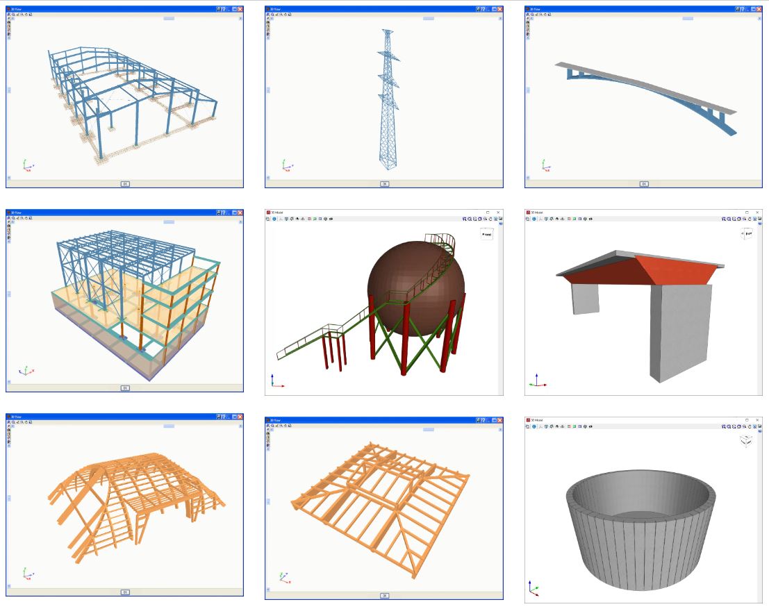
CYPE 3D analyses any type of structure with bars made of concrete, steel, composite concrete and steel, aluminium, timber, or any other material, and includes the design of connections (welded and bolted connections of rolled and welded steel I sections and hollow structural sections) and their foundations with baseplates, footings, pile caps, strap and tie beams. Timber, steel or aluminium bars and reinforced concrete columns and beams can be designed by the program. Composite concrete and steel columns can be checked by the program.
Operating as an independent program, CYPE 3D also allows the discretisation of structures using shells (flat two-dimensional elements of constant thickness whose perimeter is defined by a polygon) to analyse their forces and stresses.
It analyses, designs and checks the fire resistance of timber sections; it checks the fire resistance of steel sections and designs the protective coating for steel sections. It carries out the seismic analysis of the structure. For wind and seismic loads, it considers second-order (P-delta) effects.
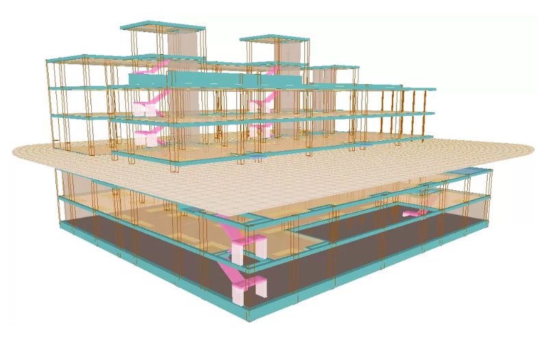
CYPE 3D also works as an independent program, as well as within CYPECAD as an integrated 3D structure.
Limit states, loadcases, combinations and loads
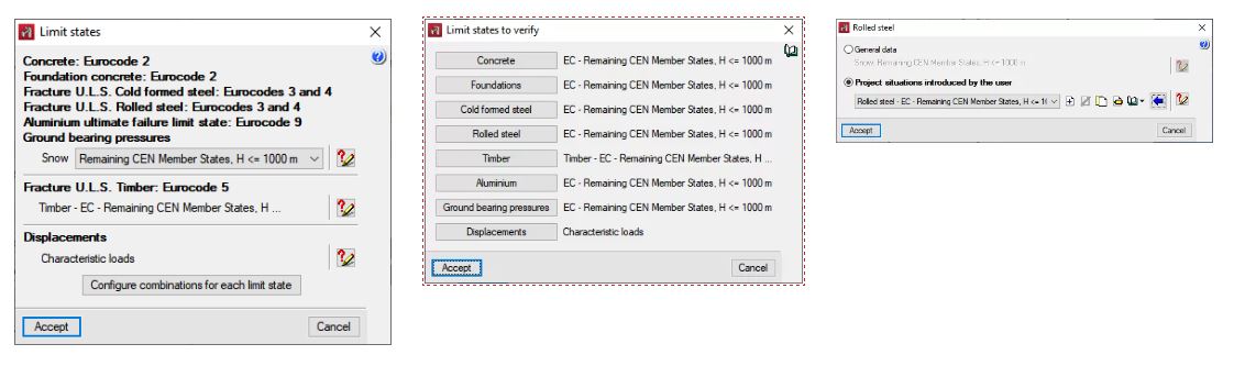
Limit states
Các trạng thái giới hạn khác nhau có thể được cấu hình cho từng vật liệu. Phần mềm cũng cho phép người dùng xem và in báo cáo về các tình huống của dự án, có và không có tải trọng địa chấn, hiển thị γ hệ số an toàn từng phần (hệ số khuếch đại tải) và ψ hệ số kết hợp cho từng loại tải (tính chất).
Loadcases and loadcase combinations
CYPE 3D automatically generates the self-weight of the entered bars that will form a self-weight loadcase. An indefinite number of additional loadcases of the same or different nature (self-weight, live load, wind, seismic or snow) can be added.
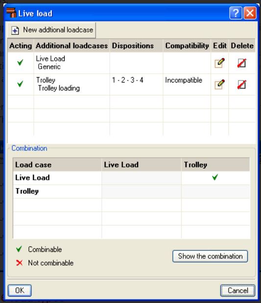
Users can define any number of simple loadcases and decide whether to combine them in a compatible, incompatible or simultaneous way. The program will automatically generate the combination of these loadcases according to the indicated conditions.
Multiple load types
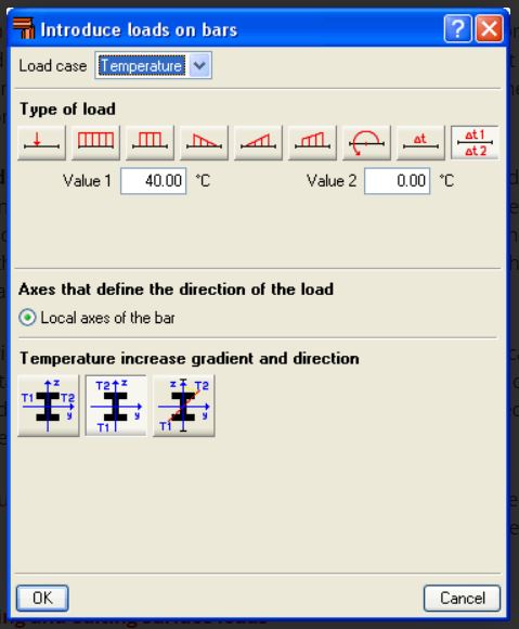
The program supports multiple types of loads such as point load, uniform load, strip load, left and right triangular load, trapezoidal load, surface with height variation, increase in uniform and variable temperature, applied moment, etc. The loads can be introduced on nodes and bars.
Surface loads are introduced on panels that have been geometrically defined by the user by means of a closed polygon. These loads can be applied on the entire surface of the panel or on polygonal surfaces contained in the panel. Users also indicate the direction of the unidirectional distribution of the loads introduced on the panel, which must be parallel to one of the sides of the panel.
Node types
The node type selection is very complete. Both internal and external fixities can be defined. External fixities allow nodes to be defined as pinned, fixed or partially fixed, elastic supports (springs), supports with free displacement according to a plane or straight line to be defined, etc
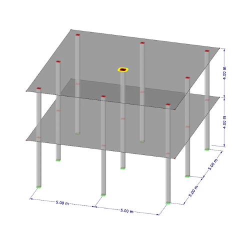
Bar structure types in CYPE 3D
CYPE 3D allows users to enter bars made of concrete, steel, composite concrete and steel, aluminium, timber or any other material.
The program designs the section reachingthe optimum size for steel, aluminium, timber or concrete bars (if their structural type has been defined as a column or beam).
Composite concrete and steel bars can be defined if they have been entered as column-type structural elements and, although they are not designed automatically, they are checked by the program with the properties indicated by the user.
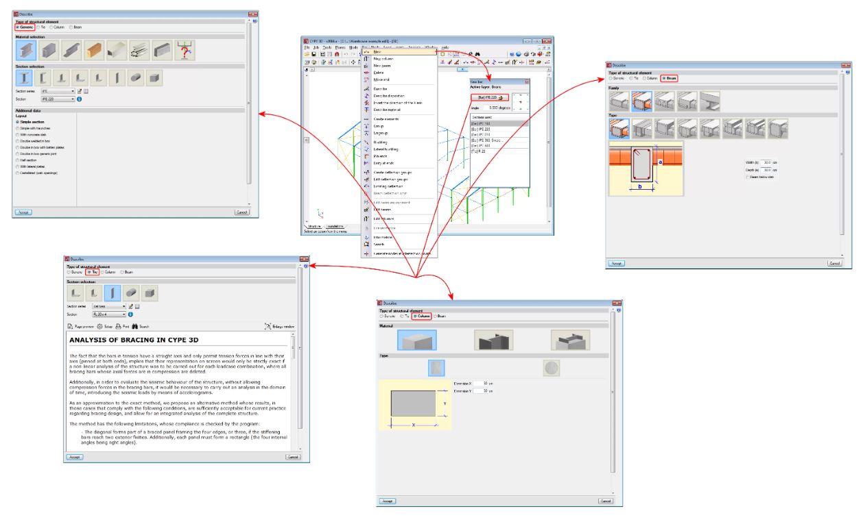
“Generic” type structural elements
Elements defined this way do not have a specific structural role in the program. The materials they can be assigned to are steel (rolled, welded or cold-formed), aluminium, timber, concrete or any other user-defined material (modulus of elasticity, Poisson’s ratio, coefficient of thermal expansion and unit weight).
The program designs the bars automatically if the assigned material is rolled, welded or cold-formed steel, aluminium or timber.
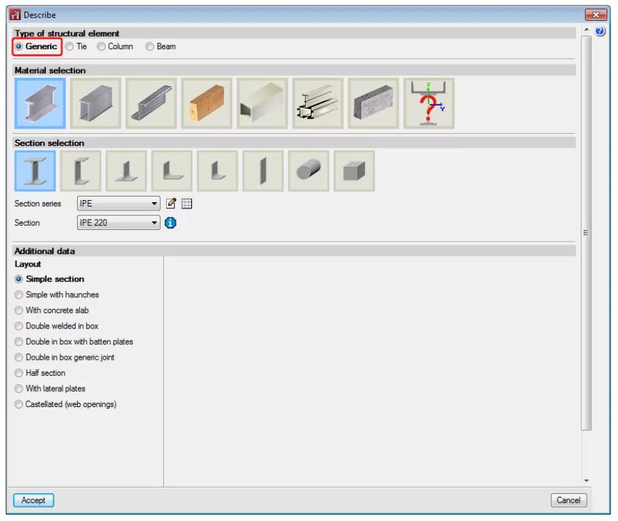
“Tie” type structural elements
The element is part of a braced frame and only works in tension. Transverse sections that can be assigned include flat bars, angles, and solid round or square bars.
More information on these structural elements can be found on the Bars defined as “Tie” type structural elements webpage.
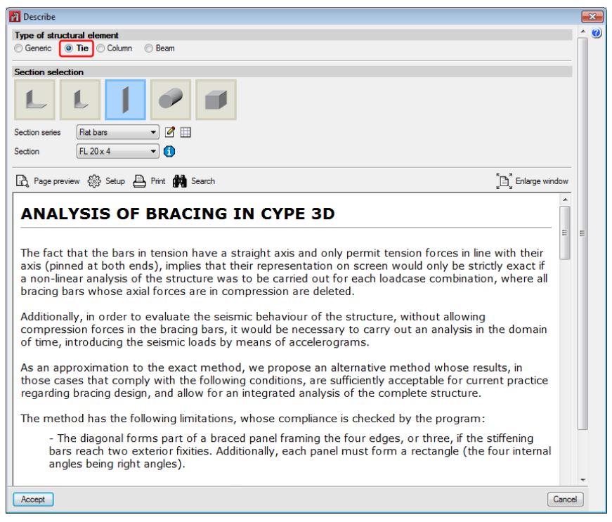
“Column” type structural elements
The element is a column and must be vertical. It accepts the following sections:
- Rectangular and circular reinforced concrete sections: More information on this module used by CYPE 3D and CYPECAD, which allows both programs to design these structural elements, can be found on the Concrete columns webpage.
- Steel sections: These can be made of rolled steel, cold-formed steel or welded steel.
- Composite steel and concrete sections: More information on this module used by CYPE 3D and CYPECAD, which allows both programs to design these structural elements, can be found on the Composite steel and concrete columns webpage.
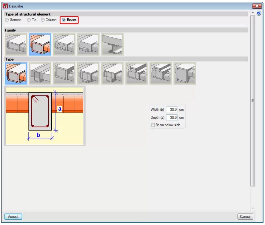
“Beam” type structural elements
The element is a beam. It cannot be vertical and must not be rotated about its longitudinal axis. It accepts the following sections:
Rectangular section, L-beam, T-beam, etc., lattice or prestressed concrete beams: More information on this module used by CYPE 3D and CYPECAD, which allows both programs to design these structural elements, can be found on the Concrete beams webpage
Steel sections: These can be made of rolled steel, cold-formed steel or welded steel. When an element is defined as a beam, the beam is composed of a single element. Nonetheless, the program allows users to define continuous beams composed of several beams.
Timber: These can be made of rectangular sections of sawn or laminated timber. More information on this module used by CYPE 3D and CYPECAD, which allows both programs to design these structural elements, can be found on the Timber sections webpage.
Other properties of bars
Buckling and lateral buckling
CYPE 3D allows users to introduce the ß buckling coefficients or buckling length, the moment coefficient and the C1 coefficient of the lateral buckling critical moment formulation (if defined by the selected code) of each bar. Each code normally provides values for these coefficients associated with different bending moment distributions between bracing points.
The program also automatically calculates the buckling length of the bars according to an approximate method, based on commonly accepted formulas, that requires users to classify the structure as a sway frame or a non-sway frame. Users can also activate the lateral buckling check for any bar.
Deflection limitation
The program allows users to limit the deflection of the bars so that the design of the sections takes into account the imposed restriction (as well as the stress, slenderness, buckling, etc). Users may limit the maximum and relative deflection, both for their absolute and relative values to the length between ends and inflection points of the deformed shape. The deflection may be defined as secant or tangent at one of its ends. An element composed of various aligned bars can also be defined so that the program checks its deflection as if it were a single bar. The dialogue boxes limiting the deflection of the bars have help captions available that perfectly define the different types of deflection that users may limit and the length that serves as a reference for the relative deflection.
Adjustments, displacements and rotations
When introducing bars, it is possible to carry out adjustments, displacements and rotations with respect to their introduction axis. The eccentricity produced by these adjustments and displacements is taken into account in the analysis, so the program allows users to consider the true relative position between bars.
Fixity coefficients and rotational stiffnesses
The program allows XY and XZ fixity coefficients or rotational stiffnesses to be assigned to the ends of elements (bars or groups of aligned bars forming an element) in these planes. Defining the rotational stiffnesses allows connections that require the consideration of their stiffnesses to rotate, such as bolted connections, to be modelled.
For each designed bolted connection, the program also analyses (for all the acting force combinations) the rotational stiffness of each element fixed to the connection and selects a rotational stiffness value for each element end, which will be that proposed by the user for re-analysing the structure.
Shells in CYPE 3D
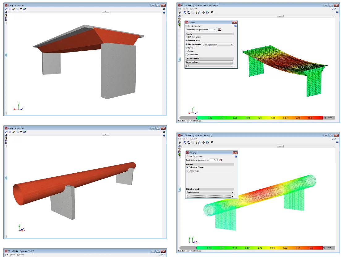
CYPE 3D allows users to define shell elements. Shells are flat two-dimensional elements with constant thickness and without openings, whose perimeter is defined by a polygon.
For analysis purposes, shells are introduced in the global stiffness matrix of the structure using a three-dimensional finite element model composed of six-node (quadratic) triangular flat shells. The type of element used is based on the overlap of two locally decoupled elements: one provides the axial stiffness (membrane forces) and the other the bending stiffness (panel forces).
The following properties can be defined for each shell
- Thickness and subgrade modulus
E in the local Z axis direction. - Material
Concrete, rolled steel, cold-formed steel, aluminium and generic material (specifying the modulus of elasticity and Poisson’s ratio). - Position
With respect to the introduction plane. - Discretisation
The density of the mesh can be controlled by defining the maximum size of the triangle in the local x and y axes. - Direction of the axes
- Internal fixity
Internal fixity between the edges and other elements of the structure. - External fixity
The external fixity of the edges can also be defined, but in this case, the fixity is applied to all the shells sharing that edge. The possible external fixity configurations are the same as those available for nodes in CYPE 3D. - Integration strips
Integration strips in shells define lines on which, for a given strip width, the forces corresponding to the shell are integrated to obtain the bar forces.
Other Function
- Fire resistance check
- Welded and bolted joints
- Baseplates
- Properties of the baseplates included in CYPE 3D
- Baseplate design options
- Baseplate checks
- Foundations
- Analysis using multiprocessors
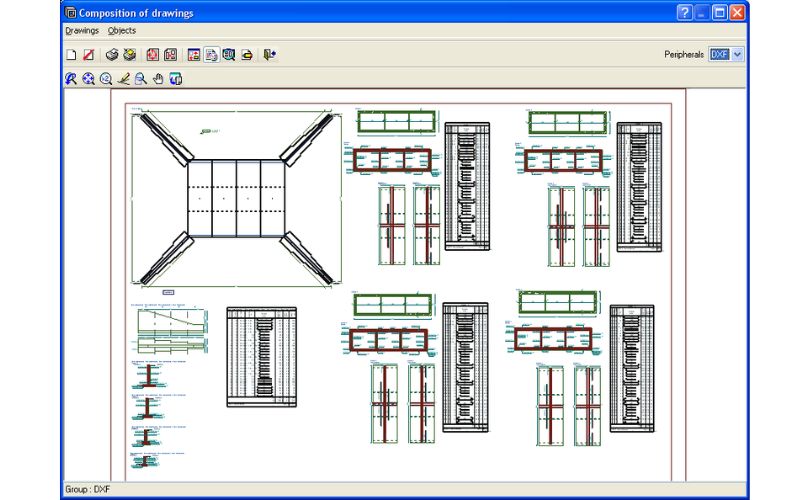
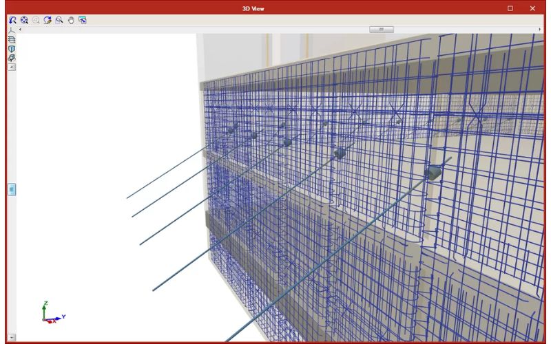
- Results, drawings and reports
Accessories

Please login to write review!