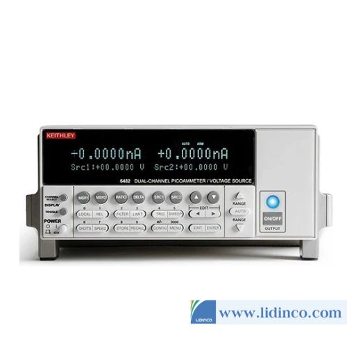
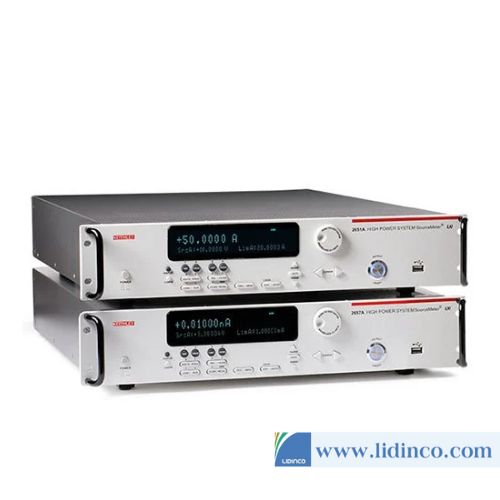
Hệ thống sourcemeter Keithley 2612B Dual-channel
Hệ thống sourcemeter Keithley 2612B Dual-channel
- Vui lòng liên hệ để kiểm tra tình trạng kho
- Tạm thời chưa có khuyến mãi cho sản phẩm này
Hotline: 0906.988.447
Liên hệ: Hồ Chí Minh
- Điện thoại: (028).3977.8269
- Email: sales@lidinco.com
- Địa chỉ: 487 Cộng Hòa, Phường 15, Quận Tân Bình, TP. HCM
Liên hệ: Bắc Ninh, Hà Nội
- Điện thoại: (0222).730.0180
- Email: bn@lidinco.com
- Địa chỉ: 184 Bình Than, Phường Võ Cường, TP. Bắc Ninh
-
 Tư vấn kĩ thuật
Miễn phí
Tư vấn kĩ thuật
Miễn phí
-
 Miễn phí vận chuyển
Đơn hàng trên 3 triệu
Miễn phí vận chuyển
Đơn hàng trên 3 triệu
Dữ liệu đang được cập nhật
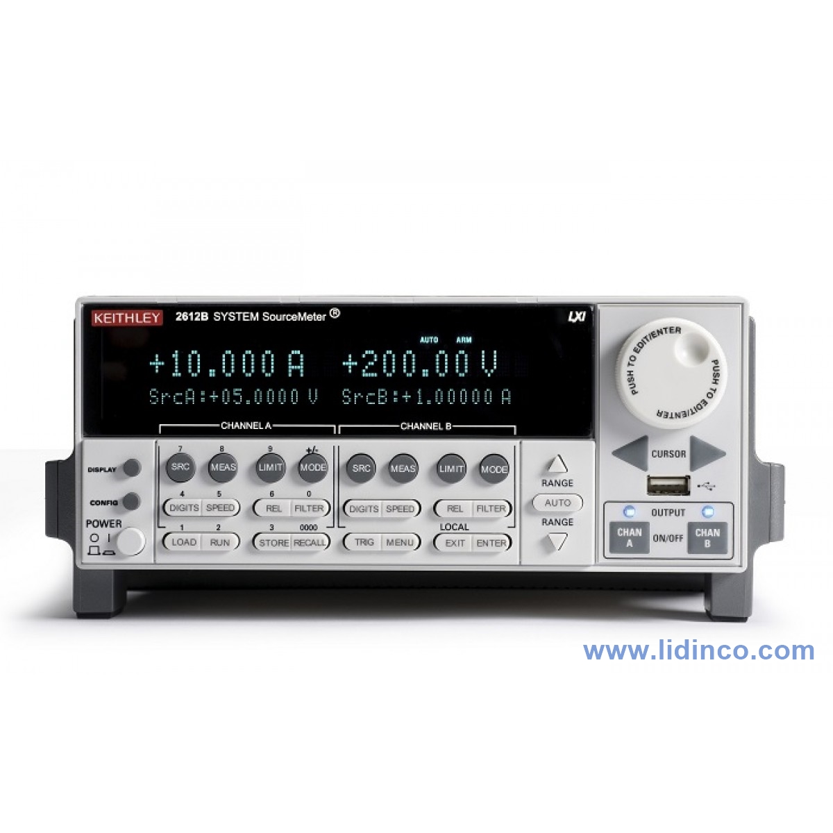
Hệ thống sourcemeter để bàn Keithley 2612B Dual-channel System SourceMeter Instrument (200V, 10A Pulse)

Thông tin sản phẩm:
The Series 2600B System SourceMeter SMU Instruments are the industry’s leading current/voltage source and measure solutions, and are built from Keithley’s 3rd generation SMU technology. The Series 2600B offers single- and dual-channel models that combine the capabilities of a Precision Power Supply, true Current Source, 6-1/2 digit DMM, Arbitrary Waveform Generator, Pulse Generator, and Electronic Load – all into one tightly integrated instrument. The result is a powerful solution that significantly boosts productivity in applications ranging from bench-top I/V characterization through highly-automated production test. For bench-top use, Series 2600B instruments feature built-in, Java-based software that enables plug & play I/V testing through any browser, on any computer, from anywhere in the world. For automated system applications, the Series 2600B’s Test Script Processor (TSP) runs complete test programs from inside the instrument for industry-best through-put. In larger, multi-channel applications, Keithley’s TSP-Link technology works together with TSP to enable high-speed, SMU-per-pin parallel testing. Because Series 2600B SourceMeter SMU Instruments have fully isolated channels that do not require a mainframe, they can be easily re-configured and re-deployed as your test applications evolve.
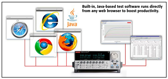
Java-based Plug & Play I/V Test Software
The Series 2600B are the only SMU instruments to feature built-in, Java-based test software that enables true plug & play I/V characterization through any browser, on any computer, from anywhere in the world. This unique capability boosts productivity across a wide range of applications such as R&D, education, QA/FA, and more. Simply connect the 2600B to the internet via the supplied LAN cable, open a browser, type in the 2600B’s I.P. address, and begin testing. Resulting data can be downloaded to a spreadsheet such as Excel for further analysis and formatting, or for inclusion in other documents or presentations.
Unmatched Throughput for Automated Test with TSP Technology
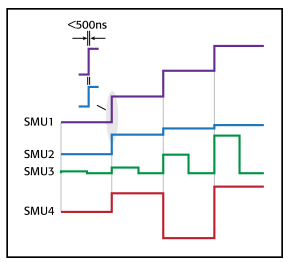 All channels in the TSP-Link
system are synch ronized to under 500ns.
For test applications that demand the highest levels of automation and throughput, the Model 2600B’s TSP technology delivers industry-best performance. TSP technology goes far beyond traditional test command sequencers… it fully embeds then executes complete test programs from within the SMU instrument itself. This virtually eliminates all the time-consuming bus communications to and from the PC controller, and thus dramatically improves overall test times.
Model 2400 Software Emulation
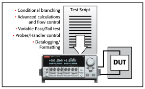 TSP technology executes complete
test programs from the
2600B’s non-volatile memory.
The Series 2600B is compatible with test code developed for Keithley’s Model 2400 SourceMeter SMU instrument. This enables an easier upgrade from Model 2400-based test systems to Series 2600B, and can improve test speeds by as much as 80%. In addition, it provides a migration path from SCPI programming to Keithley’s TSP technology, which when implemented can improve test times even more. For complete support of legacy test systems, the Model 2400’s Source-Memory-List test sequencer is also fully supported in this mode.
SMU-Per-Pin Parallel Testing with TSP-Link Technology
TSP-Link is a channel expansion bus that enables multiple Series 2600B’s to be inter-connected and function as a single, tightly-synchronized, multi-channel system. The 2600B’s TSP-Link technology works together with its’ TSP technology to enable high-speed, SMU-per-pin parallel testing. Unlike other high-speed solutions such as large ATE systems, the 2600B achieves parallel test performance without the cost or burden of a mainframe. The TSP-Link based system also enables superior flexibility, allowing for quick and easy system re-configuration as test requirements change.
Third-generation SMU Instrument Design Ensures Faster Test Times
Based on the proven architecture of earlier Series 2600 instruments, the Series 2600B’s SMU instrument design enhances test speed in several ways. For example, while earlier designs used a parallel current ranging topology, the Series 2600B uses a patented series ranging topology, which provides faster and smoother range changes and outputs that settle more quickly.
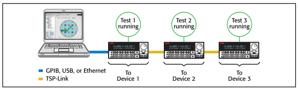
SMU-Per-Pin Parallel Testing using TSP and TSP-Link improves test throughput and lowers the cost of test.
The Series 2600B SMU instrument design supports two modes of operation for use with a variety of loads. In normal mode, the SMU instrument provides high bandwidth performance for maximum throughput. In high capacitance (high-C) mode, the SMU instrument uses a slower bandwidth to provide robust performance with higher capacitive loads.
Simplify Semiconductor Component Test, Verification, and Analysis
The optional ACS Basic Edition software maximizes the productivity of customers who perform packaged part characterization during development, quality verification, or failure analysis. Key features include:
- Rich set of easy-to-access test libraries
- Script editor for fast customization of existing tests
- Data tool for comparing results quickly
- Formulator tool that analyzes captured curves and provides a wide range of math functions
For more information about the ACS Basic Edition software, please refer to the ACS Basic Edition data sheet.
Powerful Software Tools
In addition to the embedded Java-based plug & play software and optional ACS Basic Edition software, the free Test Script Builder software tool is provided to help users create, modify, debug, and store TSP test scripts. Table 1 describes key features of Series 2600B software tools.
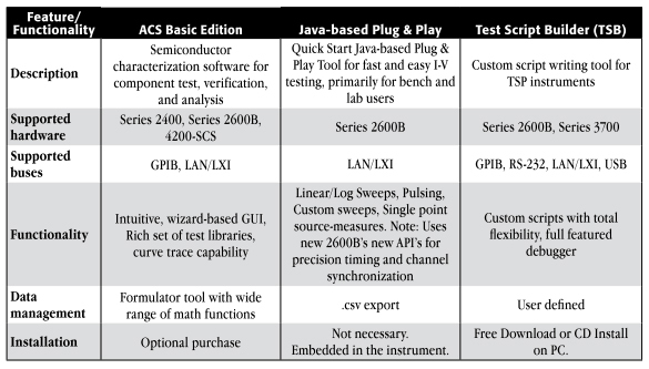 Table 1. Series 2600B software tools
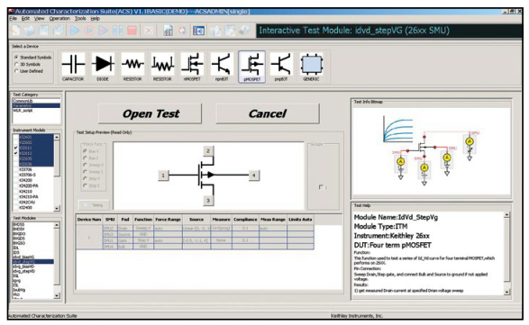
When you need to acquire data on a packaged part quickly, the wizard-based user interface of ACS Basic Edition makes it easy to find and run the test you want, like this common FET curve trace test.
Three new dual-channel bench-top models of Series 2600B offer industry-best value and performance.
For applications that do not require leading-edge system-level automation capabilities, Keithley has expanded the 2600B series to include 3 new value-priced “bench-top” models – the 2604B, 2614B, and 2634B. These models offer similar performance to Models 2602B, 2612B, and 2636B, respectively, however do not include TSP-Link, Contact Check, and Digital I/O capabilities.
Complete Automated System Solutions
Keithley’s S500 Integrated Test Systems are highly configurable, instrument-based systems for semiconductor characterization at the device, wafer, or cassette level. Built on our proven Series 2600 System SourceMeter SMU instruments, our S500 Integrated Test Systems provide innovative measurement features and system flexibility, scalable to your needs. The unique measurement capability, combined with the powerful and flexible Automated Characterization Suite (ACS) software, provides a comprehensive range of applications and features not offered on other comparable systems on the market.
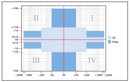
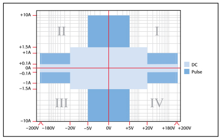
In the first and third quadrants, Series 2600B instruments operate as a source, delivering power to a load. In the second and fourth quadrants, they operate as a sink, dissipating power internally.
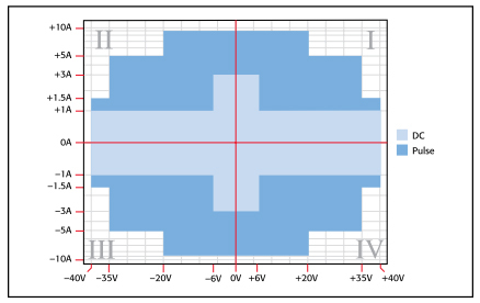
Models 2601B, 2602B, and 2604B I-V capability
Models 2611B, 2612B, and 2614B I-V capability
Models 2634B, 2635B, and 2636B I-V capability
TYPICAL APPLICATIONS
I-V functional test and characterization of a wide range of devices, including:
|
 |
 |
|
 |
|
 |
|
 |
| General Specification | ||
| IEEE-488 | IEEE-488.1 compliant. Supports IEEE-488.2 common commands and status model topology | |
| USB CONTROL (REAR) | USB 2.0 device, TMC488 protocol | |
| RS-232 | Baud rates from 300bps to 115200bps | |
| ETHERNET | RJ-45 connector, LXI Class C, 10/100BT, no auto MDIX | |
| EXPANSION INTERFACE | The TSP-Link expansion interface allows TSP enabled instruments to trigger and communicate with each other. (Not available on Model 2604B.) Cable Type: Category 5e or higher LAN crossover cable Length: 3 meters maximum between each TSP enabled instrument. | |
| LXI COMPLIANCE | LXI Class C 1.4 | |
| LXI TIMING | Total Output Trigger Response Time | 245µs min., 280µs typ., (not specified) max |
| Receive LAN[0-7] Event Delay | Unknown | |
| Generate LAN[0-7] Event Delay | Unknown | |
| DIGITAL I/O INTERFACE | Connector | 25-pin female D. |
| Input/Output Pins | 14 open drain I/O bits | |
| Absolute Maximum Input Voltage | 5.25V | |
| Absolute Minimum Input Voltage | –0.25V | |
| Maximum Logic Low Input Voltage | 0.7V, +850µA max | |
| Minimum Logic High Input Voltage | 2.1V, +570µA | |
| Maximum Source Current (flowing out of Digital I/O bit) | +960µA | |
| Maximum Sink Current @ Maximum Logic Low Voltage (0.7V) | –5.0mA. | |
| Absolute Maximum Sink Current (flowing into Digital I/O pin) | –11mA (not including Model 2604B) | |
| 5V Power Supply Pin | Limited to 600mA, solid state fuse protected. | |
| Output Enable | Active high input pulled down internally to ground with a 10kΩ resistor; when the output enable input function has been activated, each SourceMeter channel will not turn on unless the output enable pin is driven to >2.1V (nominal current = 2.1V/10kΩ = 210µA) | |
| USB FILE SySTEM (FRONT) | USB 2.0 Host | Mass storage class device |
| POWER SUPPLY | 100V to 250VAC, 50–60Hz (auto sensing), 240VA max | |
| COOLING | Forced air. Side intake and rear exhaust. One side must be unobstructed when rack mounted | |
| EMC | Conforms to European Union Directive 2004/108/EEC, EN 61326-1 | |
| SAFETY | Conforms to European Union Directive 73/23/EEC, EN 61010-1, and UL 61010-1 | |
| DIMENSIONS | 89mm high × 213mm wide × 460mm deep (3½ in × 8 3 / 8 in × 17½ in). Bench Configuration (with handle and feet): 104mm high × 238mm wide × 460mm deep (4 1 / 8 in × 9 3 / 8 in × 17½ in) | |
| WEIGHT | 2601B | 4.75kg (10.4 lbs) |
| 2602B, 2604B | 5.50kg (12.0 lbs) | |
| ENVIRONMENT:For indoor use only | Altitude | Maximum 2000 meters above sea level |
| Operating | 0°–50°C, 70% R.H. up to 35°C. Derate 3% R.H./°C, 35°–50°C | |
| Storage | –25°C to 65°C | |
| SPECIFICATION CONDITIONS |
This document contains specifications and supplemental information for the Models 2601B, 2602B, and 2604B System SourceMeter ® instruments. Specifications are the standards against which the Models 2601B, 2602B, and 2604B are tested. Upon leaving the factory, the 2601B, 2602B, and 2604B meet these specifications. Supplemental and typical values are non- warranted, apply at 23°C, and are provided solely as useful information.
Accuracy specifications are applicable for both normal and high capacitance modes. The source and measurement accuracies are specified at the SourceMeter CHANNEL A (2601B, 2602B, and 2604B) or SourceMeter CHANNEL B (2602B and 2604B) terminals under the following conditions:
|
| SOURCE SPECIFICATIONS | |||
| VOLTAGE SOURCE SPECIFICATIONS | |||
| VOLTAGE PROGRAMMING ACCURACy | |||
| Range | Programming Resolution | Accuracy (1 year) 23°C ±5°C ±(% rdg. + volts) | Typical Noise (peak-peak) 0.1Hz–10Hz |
| 100 mV | 5 µV | 0.02% + 250 µV | 20 µV |
| 1 V | 50 µV | 0.02% + 400 µV | 50 µV |
| 6 V | 50 µV | 0.02% + 1.8 mV | 100 µV |
| 40 V | 500 µV | 0.02% + 12 mV | 500 µV |
| TEMPERATURE COEFFICIENT (0°–18°C and 28°–50°C) | ±(0.15 × accuracy specification)/°C. Applicable for normal mode only. Not applicable for high capacitance mode. | ||
| MAXIMUM OUTPUT POWER AND SOURCE/SINK LIMITS | 40.4W per channel maximum. ±40.4V @ ±1.0A, ±6.06V @ ±3.0A, four quadrant source or sink operation | ||
| VOLTAGE REGULATION | Line | 0.01% of range | |
| Load | ±(0.01% of range + 100µV) | ||
| NOISE 10Hz–20MHz | <20mV peak-peak (typical), <3mV RMS (typical), 6V range | ||
| CURRENT LIMIT/COMPLIANCE | Bipolar current limit (compliance) set with single value. Minimum value is 10nA. Accuracy same as current source | ||
| OVERSHOOT | <±(0.1% + 10mV) typical. Step size = 10% to 90% of range, resistive load, maximum current limit/compliance | ||
| GUARD OFFSET VOLTAGE | <4mV typical. Current <10mA | ||
| CURRENT SOURCE SPECIFICATIONS | |||
| CURRENT PROGRAMMING ACCURACy | |||
| Range | Programming Resolution | Accuracy (1 year) 23°C ±5°C ±(% rdg. + volts) | Typical Noise (peak-peak) 0.1Hz–10Hz |
| 100 nA | 2 pA | 0.06% + 100 pA | 5 pA |
| 1 µA | 20 pA | 0.03% + 800 pA | 25 pA |
| 10 µA | 200 pA | 0.03% + 5 nA | 60 pA |
| 100 µA | 2 nA | 0.03% + 60 nA | 3 nA |
| 1 mA | 20 nA | 0.03% + 300 nA | 6 nA |
| 10 mA | 200 nA | 0.03% + 6 µA | 200 nA |
| 100 mA | 2 µA | 0.03% + 30 µA | 600 nA |
| 1 A | 20 µA | 0.05% + 1.8 mA | 70 µA |
| 3 A | 20 µA | 0.06% + 4 mA | 150 µA |
| 10 A | 200 µA | 0.5 % + 40 mA (typical) | |
| TEMPERATURE COEFFICIENT (0°–18°C and 28°–50°C) | ±(0.15 × accuracy specification)/°C | ||
| MAXIMUM OUTPUT POWER AND SOURCE/SINK LIMITS | 40.4W per channel maximum. ±1.01A @ ±40.0V , ±3.03A @ ±6.0V , four quadrant source or sink operation. | ||
| CURRENT REGULATION | Line | 0.01% of range | |
| Load | ±(0.01% of range + 100pA) | ||
| VOLTAGE LIMIT/COMPLIANCE | Bipolar voltage limit (compliance) set with a single value. Minimum value is 10mV. Accuracy is the same as voltage source | ||
| OVERSHOOT | <±0.1% typical (step size = 10% to 90% of range, resistive load; see Current Source Output Settling Time for additional test conditions). | ||
| TRANSIENT RESPONSE TIME | <70µs for the output to recover to within 0.1% for a 10% to 90% step change in load. | ||
| VOLTAGE SOURCE OUTPUT SETTLING TIME | Time required to reach within 0.1% of final value after source level command is processed on a fixed range. 100mV, 1V Ranges: <50µs typical. 6V Range: <100µs typical 40V Range: <150µs typical | ||
| CURRENT SOURCE OUTPUT SETTLING TIME | Time required to reach within 0.1% of final value after source level command is processed on a fixed range. Values below for I out × R load = 1V unless noted. 3A Range: <50µs typical. 100mV, 1V Ranges: <80µs typical (current less than 2.5A, R load >2Ω). 1A–10mA Ranges: <80µs typical (R load >6Ω) 1mA Range: <100µs typical 100µA Range: <150µs typical 10µA Range: <500µs typical 1µA Range: <2.5ms typical 100nA Range: <25ms typical | ||
| DC FLOATING VOLTAGE | Output can be floated up to ±250VDC from chassis ground | ||
| REMOTE SENSE OPERATING RANGE | Maximum voltage between HI and SENSE HI = 3V . Maximum voltage between LO and SENSE LO = 3V. | ||
| VOLTAGE OUTPUT HEADROOM | 40V Range | Max. output voltage = 42V – total voltage drop across source leads (maximum 1Ω per source lead). | |
| 6V Range | Max. output voltage = 8V – total voltage drop across source leads (maximum 1Ω per source lead). | ||
| OVER TEMPERATURE PROTECTION | Internally sensed temperature overload puts unit in standby mode | ||
| VOLTAGE SOURCE RANGE CHANGE OVERSHOOT | <300mV + 0.1% of larger range (typical). Overshoot into an 100kΩ load, 20MHz BW | ||
| CURRENT SOURCE RANGE CHANGE OVERSHOOT | <5% of larger range + 300mV/R load (typical with source settling set to SETTLE_SMOOTH_100NA). See Current Source Output Settling Time for additional test conditions. | ||
| NOTES |
|
||
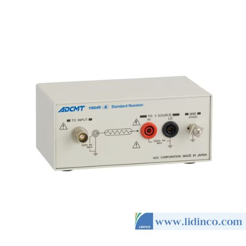
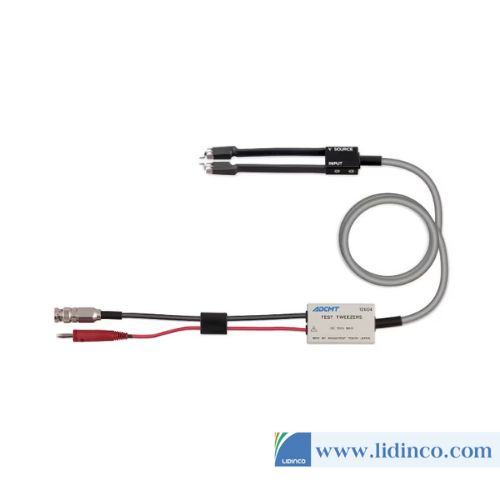
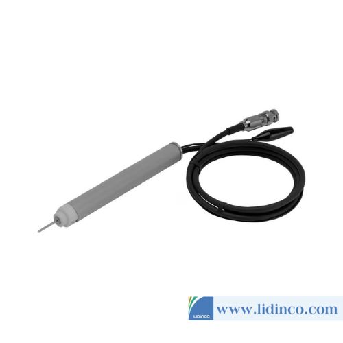
 Phu kien Keithley 2612B Dual-channel[/caption]
Phụ kiện

-
Nguồn áp:
-
Nguồn dòng:
-
Độ phân giải áp:
-
Độ phân giải dòng:
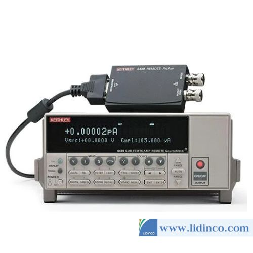
Máy đo nguồn SMU Keithley 2657A (1fA / 100nV)

-
Nguồn áp:
-
Nguồn dòng:
-
Độ phân giải áp:
-
Độ phân giải dòng:
Máy đo nguồn SMU Itech IT2800 Series
-
Nguồn áp:
-
Nguồn dòng:
-
Độ phân giải áp:
-
Độ phân giải dòng:
Máy đo nguồn SMU Keithley 2657A (1fA / 100nV)
Vui lòng đăng nhập để viết đánh giá!