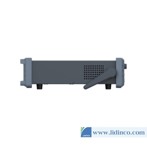
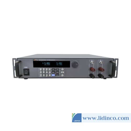
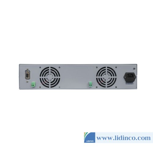
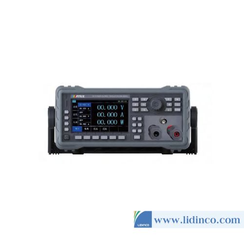
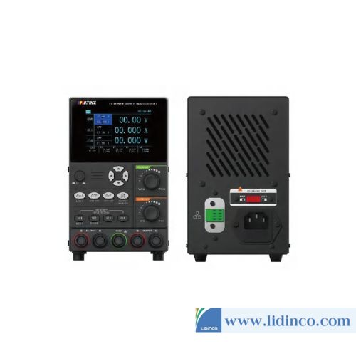
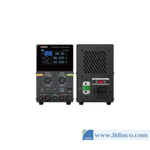
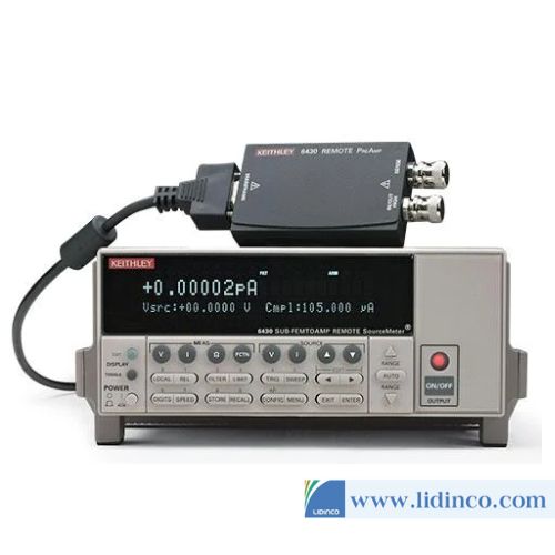
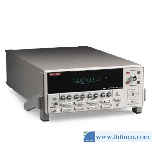
DC Power Supplies Keithley 2306-PJ 500mA
Hotline: +84 906 988 447
Head Office: Ho Chi Minh City
- Tel: +84 2839 778 269 / 3601 6797
- Email: sales@lidinco.com
- Add: 487 Cong Hoa Street, Tan Binh Ward, Ho Chi Minh City, Vietnam
Office: Bac Ninh City
- Tel: +84 222 730 0180
- Email: bn@lidinco.com
- Add: 184 Binh Than Street, Vo Cuong Ward, Bac Ninh, Vietnam
-
 Technical Counseling
100% Free
-
 Free Shipping
For 3.000.000vnd Order
Data is being updated
Description
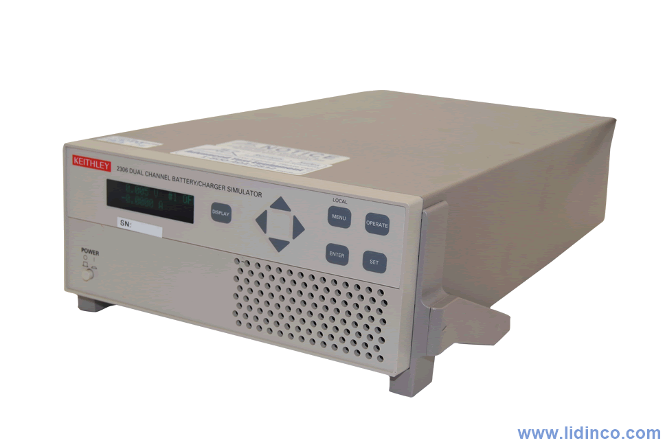
The single-channel 2302 Battery Simulator and dualchannel 2306 Battery/Charger Simulator were designed specifically for development and test applications of portable, battery-operated products, such as cellular phones, wireless devices and wearables. These precision power supplies have ultrafast transient response so they can have output characteristics identical to actual batteries. These supplies employ a unique variable output resistance so the voltage output can emulate a battery’s response (U.S. Patent No. 6,204,647). They provide stable voltage outputs, even when a device-under-test (DUT) makes the rapid transition from the standby (low current) state to the RF transmission (high current) state. In addition, they can monitor DUT power consumption by measuring both DC currents and pulse load currents. The 2302’s and the 2306’s battery-simulator channel can be programmed to operate like a discharged rechargeable battery, sinking current from a separate charger or from the 2306’s chargersimulator channel.
Features
- Ultrafast response to transient load currents
- Choice of single- or dual-channel supplies
- Optimized for development and testing of battery-powered devices
- Variable output resistance for simulating battery response (U.S. Patent No. 6,204,647)
- Pulse peak, average, and baseline current measurements
- 100nA DC current sensitivity
- Current step measure function
- Sink up to 3A
- Open sense lead detection
- Built-in digital voltmeter
Specifications
| GENERAL SPECIFICATIONS | ||
| ISOLATION (low–earth) | 22VDC max | |
| PROGRAMMING | IEEE-488.2 (SCPI) | |
| USER-DEFINABLE POWER-UP STATES | 8-position quick disconnect terminal block for output (4), sense (2), and DVM (2) | |
| TEMPERATURE COEFFICIENT (outside 23°C ±5°C) | Derate accuracy specification by (0.1 × specification)/°C | |
| OPERATING TEMPERATURE | 0° to 50°C (Derate to 70%). 0° to 35°C (Full power) | |
| STORAGE TEMPERATURE | –20° to 70°C. | |
| HUMIDITY | <80% @ 35°C non-condensing. | |
| DISPLAY TYPE | 2-line × 16 character VFD | |
| REMOTE DISPLAY/KEYPAD OPTION | Disables standard front panel | |
| DIMENSIONS | 89mm high × 213mm wide × 411mm deep (3 1 / 2 in × 8 3 / 8 in × 16 3 / 16 in) | |
| NET WEIGHT | 3.2kg (7.1 lbs) | |
| SHIPPING WEIGHT | 5.4kg (12 lbs) | |
| INPUT POWER | 100–120VAC/220–240VAC, 50 or 60Hz (auto detected at power-up) | |
| POWER CONSUMPTION | 150VA max | |
| WARRANTY | Two years parts and labor on materials and workmanship | |
| EMC | Conforms with European Union Directive directive 89/336/EEC, EN 55011, EN 50082-1, EN 61000-3-2 and 61000-3-3, FCC part 15 class B | |
| SAFETY | Conforms with European Union Directive 73/23/EEC, EN 61010-1 | |
| AC LINE LEAKAGE CURRENT | 450µA @ 110VAC, typ.; 600µA @ 220V, type | |
| RELAY CONTROL PORT | 4-channel, each capable of 100mA sink, 24V max. Total port sink capacity (all 4 combined) is 250mA max. Accepts DB-9 male plug | |
| ACCESSORIES SUPPLIED | User and service manual, output connectors mating terminal (part no. CS-846) | |
| ACCESSORIES AVAILABLE | Model 2304-DISP | Remote LCD Display/Keypad (4.6 in × 2.7 in × 1.5 in). Includes 2.7m (9 ft) cable and rack mount kit |
| DC VOLTAGE OUTPUT (2 YEARS, 23°C ± 5°C) | |||
| OUTPUT VOLTAGE | 0 to +15VDC | ||
| OUTPUT ACCURACY | ±(0.05% + 3mV) | ||
| PROGRAMMING RESOLUTION | 1mV | ||
| READBACK ACCURACY | ±(0.05% + 3mV) | ||
| READBACK RESOLUTION | 1mV | ||
| OUTPUT VOLTAGE SETTLING TIME | 5ms to within stated accuracy | ||
| LOAD REGULATION | 0.01% + 2mV | ||
| LINE REGULATION | 0.5mV | ||
| STABILITY | 0.01% + 0.5mV | ||
| MEASUREMENT TIME CHOICES | 0.01 to 10 PLC 7 , in 0.01PLC steps | ||
| AVERAGE READINGS | 1 to 10 | ||
| READING TIME | 31ms, typical | ||
| READBACK ACCURACY | High Bandwidth | Low Bandwidth | |
| Transient Recovery Time | <40µs or <60µs | <80µs or <100µs | |
| Transient Voltage Drop | <75mV or <100mV | <250mV or <400mV | |
| REMOTE SENSE | 1V max. drop in each lead. Add 2mV to the voltage load regulation specification for each 1V change in the negative output lead due to load current change. Remote sense required. Integrity of connection continually monitored. If compromised, output will turn off automatically once settable window (±0 to ±8 volts) around normal voltage exceeded. | ||
| VARIABLE OUTPUT IMPEDANCE | |
| RANGE | 0 to 1.00? in 0.01? steps. Value can be changed with output on |
| DC CURRENT (2 Years, 23°C ± 5°C) | ||
| OUTPUT CURRENT | 0–4V | 5A max |
| >4V | I MAX = 60W/(V OUT +6) (not intended to be operated in parallel) | |
| SOURCE COMPLIANCE ACCURACY | ±(0.16% + 5mA) | |
| PROGRAMMED SOURCE COMPLIANCE RESOLUTION | 1.25mA | |
| READBACK ACCURACY | 5A Range | ±(0.2% + 200µA) |
| 5mA Range | ±(0.2% + 1µA) | |
| READBACK RESOLUTION | 5A Range | 100µA |
| 5mA Range | 0.1µA | |
| CURRENT SINK CAPACITY | 0–5V | 3A max |
| 5V–15V | Derate 0.2A per volt above 5V. Compliance setting controls sinking | |
| LOAD REGULATION | 0.01% + 1mA | |
| LINE REGULATION | 0.5mA | |
| STABILITY | 0.01% + 50µA | |
| MEASUREMENT TIME CHOICES | 0.01 to 10 PLC , in 0.01PLC steps | |
| AVERAGE READINGS | 1 to 10 | |
| READING TIME | 31ms, typical | |
| PULSE CURRENT MEASUREMENT OPERATION | ||
| TRIGGER LEVEL | 5A Range | 5mA to 5A, in 5mA steps |
| 1A Range | 1mA to 1A, in 1mA steps | |
| 100mA Range | 0.1mA to 100mA, in 100µA steps | |
| TRIGGER DELAY | 0 to 100ms, in 10µs steps | |
| INTERNAL TRIGGER DELAY | 15µs | |
| HIGH/LOW/AVERAGE MODE | Measurement Aperture Settings | 33.3µs to 833ms, in 33.3µs steps |
| Average Readings | 1 to 100 | |
| PULSE CURRENT MEASUREMENT ACCURACY 11 (2 Years, 23°C ±5°C) | APERTURE | ACCURACY ±(% reading + offset + rms noise 10 ) |
| <100 µs | 0.2% + 900 µA + 2 mA | |
| 100 µs – 200 µs | 0.2% + 900 µA + 1.5mA | |
| 200 µs – 500 µs | 0.2% + 900 µA + 1 mA | |
| 500 µs – <1 PLC | 0.2% + 600 µA + 0.8mA | |
| 1 PLC | 0.2% + 400 µA + 0 mA | |
| >1 PLC | 0.2% + 400 µA + 100 µA | |
| PULSE CURRENT MEASUREMENT OPERATION | |
| MEASUREMENT APERTURE | 33.3µs |
| CONVERSION RATE | 3650/second, typical |
| INTERNAL TRIGGER DELAY | 15µs |
| NUMBER OF SAMPLES | 1 to 5000 |
| TRANSFER SAMPLES ACROSS IEEE BUS IN BINARY MODE | 4800 bytes/s, typical |
| LONG INTEGRATION MODE CURRENT MEASUREMENT | |
| MEASUREMENT TIME | 850ms (840ms) to 60 seconds in 1ms steps |
| DIGITAL VOLTMETER INPUT (2 Years, 23°C ± 5°C) | |
| INPUT VOLTAGE RANGE | –5 to +30VDC |
| INPUT IMPEDANCE | 2M? typical |
| MAXIMUM VOLTAGE (either input terminal) WITH RESPECT TO OUTPUT LOW | –5V, +30V |
| READING ACCURACY | ±(0.05% + 3mV) |
| READING RESOLUTION | 1mV |
| CONNECTOR | HI and LO input pair part of Output #1’s terminal block |
| MEASUREMENT TIME CHOICES | 0.01 to 10 PLC 7 , in 0.01PLC steps |
| AVERAGE READINGS | 1 to 10 |
Accessories
- User and service manual
- output connectors mating terminal (part no. CS-846)

-
Voltage Source:
-
Current Source:
-
Voltage Resolution:
-
Current Resolution:
High Power SourceMeter Keithley 2657A (1fA / 100nV)
Please login to write review!

