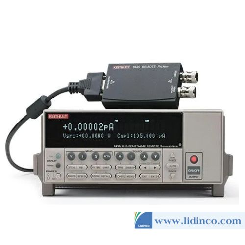
Hệ thống sourcemeter Keithley 2790
Hotline: +84 906 988 447
Head Office: Ho Chi Minh City
- Tel: +84 2839 778 269 / 3601 6797
- Email: [email protected]
- Add: 487 Cong Hoa Street, Tan Binh Ward, Ho Chi Minh City, Vietnam
Office: Bac Ninh City
- Tel: +84 222 730 0180
- Email: [email protected]
- Add: 184 Binh Than Street, Vo Cuong Ward, Bac Ninh, Vietnam
-
 Technical Counseling
100% Free
Technical Counseling
100% Free
-
 Free Shipping
For 3.000.000vnd Order
Free Shipping
For 3.000.000vnd Order
Data is being updated
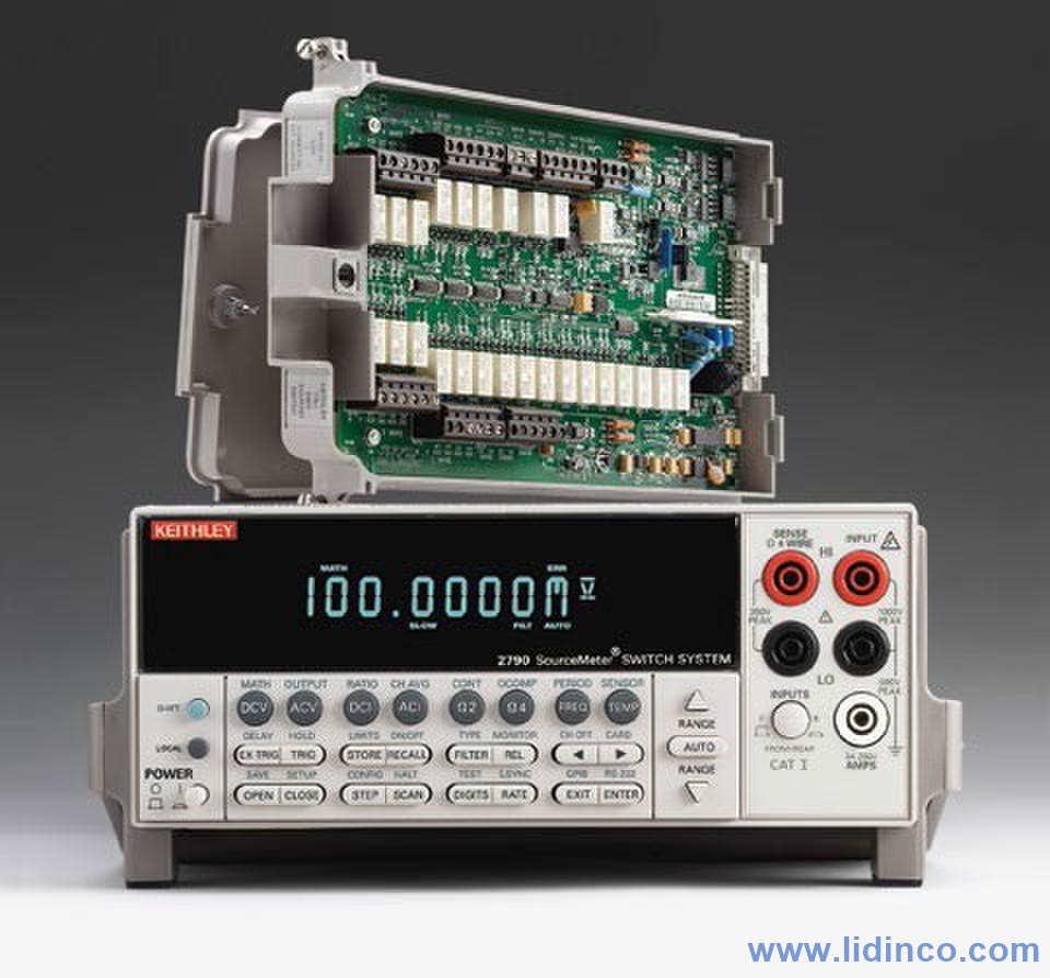
Hệ thống sourcemeter để bàn Keithley 2790 SourceMeter Switch System
Thông tin sản phẩm:
The Model 2790 SourceMeter Switch System is a high voltage, multichannel resistance measurement solution that speeds and simplifies electrical checks of airbag inflators and a variety of other automotive electrical test applications. It is the only commercial instrument that combines all the sourcing, measurement, and signal routing capabilities required to measure insulation resistance and conductor continuity in one compact, affordable package. Through the use of plug-in source/switch modules, the Model 2790 provides programmable high voltage and low current sourc-ing, plus multichannel switching support. This unique combination of capabilities establishes a new standard for price and performance in airbag inflator and other test applications.
Measure Extreme Resistances with Constant Current or Constant Voltage
The Model 2790 uses the forced constant-current method to measure resistances less than 1kΩ. In this technique, the instrument sources a constant current (I) to the resistance and measures the resulting voltage (V). The amount of current sourced is programmable from 0–50mA. Resistance (R) is calculated (and displayed) using the known current and measured voltage (R = V/I). A 20mV dry circuit clamp is available at sourcing levels up to 1mA for preserving the oxide layers on connectors and other components.
For the 1MΩ to 1GΩ resistance ranges, the forced constant-voltage method is used to measure high resistance. This technique optimizes settling speed and reduces noise, allowing faster, high quality insulation resistance measurements. In addition, by applying high voltages (50–500V), the Model 2790 stresses a dielectric while simultaneously measuring its insulation resistance.
In addition to the resistance measurement functions available through the plug-in source/switch modules, the Model 2790’s built-in DMM allows it to make a full range of high precision resistance measurements as well as AC/DC voltage and current, frequency, and temperature measurements. These DMM functions are available either through front panel jacks or through the addition of a Model 7702 40-channel scanner module. In addition to the shorts/open testing performed with the standard Model 7751, 7752, and 7753 switch/control modules, a wide range of supporting measurements can be made. These supporting measurements simplify creating integrated test solutions for hybrid applications, such as testing complex automotive seating systems, which increasingly combine airbag inflators and seatbelt pre- tensioners, seat heaters, switches, motors, etc.
Newly Enhanced Memory Pattern Test Sequencer
The memory pattern test sequencer allows the mainframe to store and execute pre-programmed test sequences for increased testing throughput. Test setups can be stored as unique memory locations and either recalled by number as needed or scanned in sequence to maximize the number of tests per unit time without command transfer delays due to communication or controller.
Match the System Configuration to the Application
The Model 2790 is available in a variety of configurations to match specific application requirements:
- The Model 2790-H is a single-module system designed for both low current and high voltage ohms (10MΩ to 1GΩ) applications. This “base” system provides all the capabilities needed for electrical testing of either single- or dual-stage inflators in single position test stands (for example, test stands that test only one single- or dual-stage airbag at a time).
- The Model 2790-A, which is similar to the Model 2790-H, enables high voltage ohms measurements down to 1MΩ.
- The Model 2790-HH is configured for applications that require parallel testing or high voltage “soaking.” Like the Model 2790-H, it is designed for both low current and high voltage ohms applications and can test either single- or dual-stage inflators. However, with two plug-in modules, it also has the capacity to test two inflators at once, maximizing test throughput.
- The Model 2790-HL is designed for applications where it is preferable to segregate high voltage sourcing/ohms measurement and low current sourcing/ohms measurement into two separate modules. This design was developed for use in combination testing applications, such as inflator electrical checks of safety steering wheel or seat assemblies that also include switch or other ancillary device tests.
- The Model 2790-L is configured for low voltage source/ohms-only measurement applications, such as continuity-only testing of side/seat airbags and seatbelt pre-tensioners or other programmable I-source resistance applications in which high voltage resistance testing is not required but precise control of source current is.
- With the addition of a Model 7702 40-channel differential multiplexer module (part of the Integra family of switch/measure solutions), the Model 2790-A, -H, or -L + Model 7702 opens the door to higher channel count applications, such as hi-pot/continuity testing of connectors, harnesses, and power distribution devices up to 500V (internally sourced) up to 40 channels.
Broad Range of Measurement Capabilities
The Model 2790’s built-in DMM can make a wide variety of general purpose measurements:
- DC voltage measurements from 0.1µV to 1000V
- AC voltage measurements from 0.1µV to 750V
- DC current measurements from 10nA to 3A
- AC current measurements from 1µA to 3A
- 2-wire resistance measurements from 100µΩ to 120MΩ
- 4-wire resistance measurements from 100µΩ to 120MΩ
- Frequency measurements from 3Hz to 500kHz
- Period measurements from 333ms to 2µs
- Temperature measurements from –200°C to 630°C (thermistors and 4-wire RTDs)
Additional features of the Model 2790 mainframe include:
- Setup storage—Up to four instrument setups can be saved and recalled.
- Offset-compensated ohms—A two-measurement process for 4-wire ohms to cancel the effects of thermoelectric EMFs. Available for the 100Ω, 1kΩ, and 10kΩ ranges.
- Math—m/X+b, mX+b, percent, and four special math functions provide convenient manipulation of raw readings.
- Relative—Null offsets establish baseline values.
- Ratio and channel average—Ratio and average calculations for two switching module channels (7702)
- Buffer—Store up to 55,000 readings in the internal buffer
- Limits—Two sets of high and low reading limits to test devices
- Digital I/O port—Five digital limit test output lines to control external circuitry. An external trigger input can also be accessed at this port
- Trigger Link—Separate connector with input and output signals.
- Monitor—The Model 2790 can monitor a selected channel. A scan can be triggered to start when the monitor detects that a reading limit has been reached (7702).
- Remote interface—Model 2790 can be controlled using the IEEE-488 interface (GPIB) or the RS-232 interface.
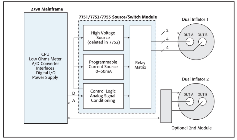
Example Application – Dual Stage Airbag Inflator Testing–One or Two
Example Application – 40-channel Wiring Harness Testing
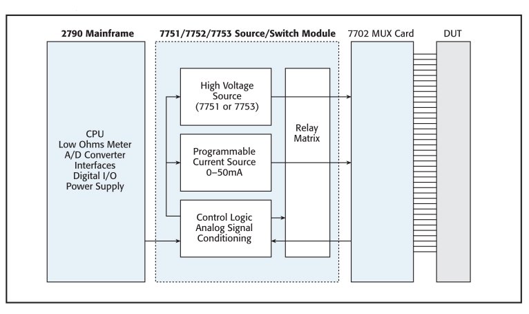
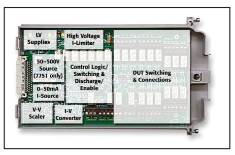
Three source/switch plug-in modules provide the Model 2790 with programmable high voltage and low current sources, connection switching, and signal conditioning circuitry.
Applications:
- Automotive airbag inflator/module electrical functional tests
- Seatbelt pre-tensioner actuator/module functional electrical check
- High speed, parallel soak, dual inflator, or dual test station electrical check
- Pinched wire, high voltage, insulation resistance testing in automotive seats, avionics, etc.
- Multipin connector/harness continuity and leakage resistance measurements
- Multicontact/switch dry circuit continuity and leakage tests
- Automotive power/fuse center continuity and leakage resistance characterization
- PCB/PWB and general purpose short/open circuits testing
| GENERAL SPECIFICATIONS | ||
| POWER SUPPLY | 100V / 120V / 220V / 240V +10%, -5%. | |
| LINE FREQUENCY | 50/60Hz, automatically sensed at power-up | |
| POWER CONSUMPTION | 28VA | |
| OPERATING ENVIRONMENT | Specified for 0°C to 40°C. Specified to 60% R.H. at 35°C | |
| STORAGE ENVIRONMENT | -40°C to 70°C | |
| BATTERY | Lithium battery-backed memory, 3 years @ 23°C. | |
| WARRANTY | 1 year | |
| EMC | Conforms to European Union Directive 89/336/EEC EN61326-1 | |
| SAFETY | Conforms to European Union Directive 73/23/EEC EN61010-1, CAT I | |
| VIBRATION | MIL-PRF-28800F Class 3, Random | |
| WARM-UP | 2 hours to rated accuracy | |
| DIMENSIONS | Rack Mounting | 89mm high × 213mm wide × 370mm deep (3.5 in. × 8.375 in. × 14.563 in.). |
| Bench Configuration (with handle and feet) | 104mm high × 238mm wide × 370mm deep (4.125 in. × 9.375 in. × 14.563 in.). | |
| SHIPPING WEIGHT | 6.5kg (14 lbs) | |
| DIGITAL I/O | 2 inputs, 1 for triggering and 1 for hardware interlock. 5 outputs, 4 for Reading Limits and 1 for Master Limit. Outputs are TTL compatible or can sink 250mA, diode clamped to 33V | |
| EARTH ISOLATION | 500Vpeak, >10G? and <150pF any terminal to chassis | |
| TRIGGERING AND MEMORY | Window Filter Sensitivity | 0.01%, 0.1%, 1%, 10%, or Full-scale of range (none) |
| Reading Hold Sensitivity | 0.01%, 0.1%, 1%, or 10% of reading | |
| Trigger Delay | 0 to 99 hrs (1ms step size). | |
| External Trigger Delay | <2ms | |
| External Trigger Jitter | <1ms | |
| Memory Size | 55,000 readings | |
| MATH FUNCTIONS | Rel, Min/Max/Average/Std Dev/Peak-to-Peak (of stored reading), Limit Test, %, mX + b and m(1/X) +b with user defined units displayed | |
| REMOTE INTERFACE | GPIB (IEEE-488.2) and RS-232C. SCPI (Standard Commands for Programmable Instruments) | |
| ACCESSORIES SUPPLIED | User Manual and Reference Manual, Screw Driver | |
| MODULES SUPPORTED | Models 7751, 7752, and 7702. | |
| MAINFRAME FUNCTION SPECIFICATION | |
| AC System Speeds | |
| RANGE CHANGES | 4/s (3/s) |
| FUNCTION CHANGES | 4/s (3/s) |
| AUTORANGE TIME | < 3s |
| ASCII READINGS TO RS-232 (19.2k baud) | 50/s |
| MAX. INTERNAL TRIGGER RATE | 300/s |
| MAX. EXTERNAL TRIGGER RATE | 250/s. |
| AC System Speeds | |
|
|
| Internal Scanner Speeds | |
| Into and Out of Memory to GPIB | 7702 Scanning DCV: 60/s |
| Internal Scanner Speed Notes | |
| Speeds are 60Hz or 50Hz operation using factory default conditions (*RST). NPLC = 0.01. Auto Zero off, Auto Range off, and Display off. Sample count =1024. Includes measurement and binary data transfer out GPIB. | |
| AC MEASUREMENT SPECIFICATIONS | ||||||||
| Function | Range | Resolution | All Ranges Calibration Cycle | All Ranges Accuracy: ±(% of reading + % of range), 23°C ±5 °C | ||||
| 3 Hz- 10 Hz | 10 Hz- 20 kHz | 20 kHz- 50 kHz | 50 kHz- 100 kHz | 100 kHz- 300 kHz | ||||
| Voltage | 100.0000mV | 0.1µV | 90Days | 0.35 + 0.03 | 0.05 + 0.03 | 0.11 + 0.05 | 0.6 + 0.08 | 4.0 + 0.5 |
| 1.000000V | 1.0µV | |||||||
| 10.00000V | 10µV | 1Year | 0.35 + 0.03 | 0.06 + 0.03 | 0.12 + 0.05 | 0.6 + 0.08 | 4.0 + 0.5 | |
| 100.0000V | 100µV | |||||||
| 750.000V | 1.0µV | |||||||
| (Temp. Coeff.) /°C | 0.035 + 0.003 | 0.005 + 0.003 | 0.006 + 0.005 | 0.01 + 0.006 | 0.03 + 0.01 | |||
| 3 Hz- 10 Hz | 10 Hz- 5 kHz | |||||||
| Current | 1.000000A | 1.0µA | 90Day/ 1Year | 0.30 + 0.04 | 0.10 + 0.04 | |||
| 3.00000A | 10µA | 0.35 + 0.06 | 0.15 + 0.06 | |||||
| (Temp. Coeff.) /°C | 0.035 + 0.006 | 0.015 + 0.006 | ||||||
| (3 Hz -500kHz) | (333ms- 2µs) | |||||||
| Frequency and Period | 100mV to 750V | 0.333 ppm | 90Day/ 1Year | 100ppm + 0.333ppm | (SLOW, 1s gate) | |||
| 3.33 ppm | 100 ppm + 3.33 ppm | (MED, 100ms gate) | ||||||
| 33.3 ppm | 100ppm + 33.3ppm | (FAST, 10ms gate) | ||||||
| Additional Uncertainty ±(% of reading) | ||
| Low Frequency Uncertainty | MED | FAST |
| 20Hz - 30Hz | 0.3 | |
| 30Hz - 50Hz | 0 | |
| 50Hz - 100Hz | 0 | 1.0 |
| 100Hz - 200Hz | 0 | 0.18 |
| 200Hz - 300Hz | 0 | 0.10 |
| > 300Hz | 0 | 0 |
| CREST FACTOR | ||
| Additional Uncertainty | 0.05 0.15 0.30 | |
| AC MEASUREMENT CHARACTERISTICS | ||
| AC Volts | MEASUREMENT METHOD | AC-coupled, True RMS |
| INPUT IMPEDANCE | 1MΩ ±2% // by <100pF | |
| INPUT PROTECTION | 1000Vp or 400VDC, 300Vrms with 7702 module | |
| AC Current | MEASUREMENT METHOD | AC-coupled, True RMS |
| SHUNT RESISTANCE | 0.1Ω | |
| BURDEN VOLTAGE | 1A <0.3Vrms, 3A <1Vrms. Add 1Vrms when used with 7702 modules | |
| INPUT PROTECTION | 3A, 250V fuse | |
| Frequency and Period | MEASUREMENT METHOD | Reciprocal Counting technique |
| GATE TIME | SLOW 1s, MED 100ms, and FAST 10ms | |
| AC General | AC CMRR | 70dB. |
| MAXIMUM CREST FACTOR | 5 at full-scale | |
| VOLT HERTZ PRODUCT | <= 8 × 10 | |
| AC OPERATING CHARACTERISTICS | |||||
| 60Hz (50Hz) Operation | Function | Digits | Readings/s | Rate | Bandwidth |
| ACV, ACI | 6.5 | 2s/Reading | SLOW | 3 Hz-300kHz | |
| 6.5 | 1.4 (1.1) | MED | 30 Hz-300kHz | ||
| 6.5 | 4.8 (4) | MED | 30 Hz-300kHz | ||
| 6.5 | 35 (28) | FAST | 300 Hz-300kHz | ||
| Frequency, Period | 6.5 | 1 (1) | SLOW | 3 Hz-300kHz | |
| 5.5 | 9 (9) | MED | 30 Hz-300kHz | ||
| 4.5 | 35 (35) | FAST | 300 Hz-300kHz | ||
| 4.5 | 65 (65) | FAST | 300 Hz-300kHz | ||
- Keithley 7702 40 Channel Differential Multiplexer W/Sc
- Keithley 7751 500V Source/Switch Card
- Keithley 7752 Source/Switch Card
- Keithley 7753 High Volt Source Switch Module
Accessories


-
Voltage Source:
-
Current Source:
-
Voltage Resolution:
-
Current Resolution:
High Power SourceMeter Keithley 2657A (1fA / 100nV)
-
Voltage Source:
-
Current Source:
-
Voltage Resolution:
-
Current Resolution:
High Power SourceMeter Keithley 2657A (1fA / 100nV)
Please login to write review!