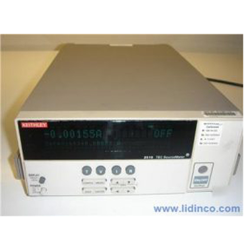
Keithley 2510 TEC SourceMeter
Hotline: +84 906 988 447
Head Office: Ho Chi Minh City
- Tel: +84 2839 778 269 / 3601 6797
- Email: [email protected]
- Add: 487 Cong Hoa Street, Tan Binh Ward, Ho Chi Minh City, Vietnam
Office: Bac Ninh City
- Tel: +84 222 730 0180
- Email: [email protected]
- Add: 184 Binh Than Street, Vo Cuong Ward, Bac Ninh, Vietnam
-
 Technical Counseling
100% Free
Technical Counseling
100% Free
-
 Free Shipping
For 3.000.000vnd Order
Free Shipping
For 3.000.000vnd Order
Data is being updated
Hệ thống sourcemeter để bàn Keithley 2510 TEC SourceMeter
Thông tin sản phẩm:

The Models 2510 and 2510-AT TEC SourceMeter instruments enhance Keithley’s CW (Continuous Wave) test solution for high speed LIV (light-current-voltage) testing of laser diode modules. These 50W bipolar instruments were developed in close cooperation with leading manufacturers of laser diode modules for fiberoptic telecommunications networks. Designed to ensure tight temperature control for the device under test, the Model 2510 was the first in a line of highly specialized instruments created for telecommunications laser diode testing. It brings together Keithley’s expertise in high speed DC sourcing and measurement with the ability to control the operation of a laser diode module’s ThermoElectric Cooler or TEC (sometimes called a Peltier device) accurately.
The Model 2510-AT expands the capability of the Model 2510 by offering autotuning capability. P, I, and D (proportional, integral, and derivative) values for closed loop temperature control are determined by the instrument using a modified Zeigler-Nichols algorithm. This eliminates the need for users to determine the optimal values for these coefficients experimentally. In all other respects, the Model 2510 and Model 2510-AT provide exactly the same set of features and capabilities.
The SourceMeter Concept
The Model 2510 and Model 2510-AT draw upon Keithley’s unique Source Meter concept, which combines precision voltage/current sourcing and measurement functions into a single instrument. SourceMeter instruments provide numerous advantages over the use of separate instruments, including lower acquisition and maintenance costs, the need for less rack space, easier system integration and programming, and a broad dynamic range.
Part of a Comprehensive LIV Test System
In a laser diode CW test stand, the Model 2510 or Model 2510-AT can control the temperature of actively cooled optical components and assemblies (such as laser diode modules) to within ±0.005°C of the user-defined setpoint. During testing, the instrument measures the internal temperature of the laser diode module from any of a variety of temperature sensors, then drives power through the TEC within the laser diode module in order to maintain its temperature at the desired setpoint.
Active temperature control is very important due to the sensitivity of laser diodes to temperature changes. If the temperature varies, the laser diode’s dominant output wavelength may change, leading to signal overlap and crosstalk problems.
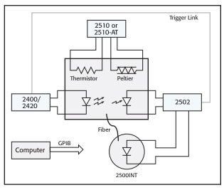
Figure 1. The capabilities of the Models 2510 and
2510-AT are intended to complement those of other
Keithley instruments often used in laser diode module
LIV testing, including the Model 2400 and 2420
SourceMeter instruments, the Model 2502 Dual Photo-
diode Meter, and the Model 2500INT Integrating Sphere.
Autotuning Function
The Model 2510-AT Autotuning TEC SourceMeter instrument offers manu facturers the ability to automatically tune the temperature control loop required for CW testing of optoelectronic components such as laser diode modules and thermo-optic switches. This capability eliminates the need for time-consuming experimentation to determine the optimal P-I-D coefficient values.
The Model 2510-AT’s P-I-D Auto-Tune software employs a modified Ziegler-Nichols algorithm to determine the coefficients used to control the P-I-D loop. This algorithm ensures that the final settling perturbations are damped by 25% each cycle of the oscillation. The autotuning process begins with applying a voltage step input to the system being tuned (in open loop mode) and measuring several parameters of the system’s response to this voltage step function. The system’s response to the step function is illustrated in Figure 2. The lag time of the system response, the maximum initial slope, and the TAU [63% (1/e)] response time are measured, then used to generate the Kp (proportional gain constant), Ki (integral gain constant), and Kd (derivative gain constant) coefficients.
The autotuning function offers users a choice of a minimum settling time mode or a minimum overshoot mode, which provides the Model 2510-AT with the flexibility to be used with a variety of load types and devices. For example, when controlling a large area TEC in a test fixture optimized for P, I, and D values, minimum overshoot protects the devices in the fixture from damage (Figure 3). For temperature setpoints that do not approach the maximum specified temperature for the device under test, the minimum settling time mode can be used to speed up the autotuning function (Figure 4).
50W Output
As the complexity of today’s laser diode modules increases, higher power levels are needed in temperature controllers to address the module’s cooling needs during production test. The 50W (5A @ 10V) output allows for higher testing speeds and a wider temperature setpoint range than other, lower-power solutions.
High Stability P-I-D Control
When compared with other TEC controllers, which use less sophisticated P-I (proportional-integral) loops and hardware control mechanisms, this instrument’s software-based, fully digital P-I-D control provides greater temperature stability and can be easily upgraded with a simple firmware change. The resulting temperature stability (±0.005°C short term, ±0.01°C long term) allows for very fine control over the output wavelength and optical power of the laser diode module during production testing of DC characteristics. This improved stability gives users higher confidence in measured values, especially for components or sub-assemblies in wavelength multiplexed networks. The derivative component of the instrument’s P-I-D control also reduces the required waiting time between making measurements at various temperature setpoints. The temperature setpoint range of –50°C to +225°C covers most of the test requirements for production testing of cooled optical components and sub-assemblies, with a resolution of ±0.001°C.
Before the introduction of the Model 2510-AT, configuring test systems for new module designs and fixtures required the user to determine the best ombination of P, I, and D coefficients through trial-and-error experimentation. The Model 2510-AT’s autotuning function uses the modified Zeigler-Nichols algorithm to determine the optimal P, I, and D values automatically.
Adaptable to Evolving DUT Requirements
The Model 2510 and Model 2510-AT are well suited for testing a wide range of laser diode modules because they are compatible with the types of temperature sensors most commonly used in these modules. In addition to 100Ω, 1kΩ, 10kΩ, and 100kΩ thermistors, they can handle inputs from 100Ω or 1kΩ RTDs, and a variety of solid-state temperature sensors. This input flexibility ensures their adaptability as the modules being tested evolve over time.
Programmable Setpoints and Limits
Users can assign temperature, current, voltage, and thermistor resistance setpoints. The thermistor resistance setpoint feature allows higher correlation of test results with actual performance in the field for laser diode modules because reference resistors are used to control the temperature of the module. Programmable power, current, and temperature limits offer maximum protection against damage to the device under test.
Accurate Real-Time Measurements
Both models can perform real-time measurements on the TEC, including TEC current, voltage drop, power dissipation, and resistance, providing valuable information on the operation of the thermal control system.
Peltier (TEC) Ohms Measurement
TEC devices are easily affected by mechanical damage, such as sheer stress during assembly. The most effective method to test a device for damage after it has been incorporated into a laser diode module is to perform a low-level AC (or reversing DC) ohms measurement. If there is a change in the TEC’s resistance value when compared with the manufacturer’s specification, mechanical damage is indicated. Unlike a standard DC resistance measurement, where the current passing through the device can produce device heating and affect the measured resistance, the reversing DC ohms method does not and allows more accurate measurements.
| General Specifications | |||||||||||
| SOURCE OUTPUT MODES | Fixed DC level. | ||||||||||
| PROGRAMMABILITY | IEEE-488 (SCPI-1995.0), RS-232, 3 user- definable power-up states plus factory default and *RST. | ||||||||||
| POWER SUPPLY | 90V to 260V rms, 50–60Hz, 75W. | ||||||||||
| EMC | Complies with European Union Directive 98/336/EEC (CE marking require ments), FCC part 15 class B, CTSPR 11, IEC 801-2, IEC 801-3, IEC 801-4. | ||||||||||
| VIBRATION | MIL-PRF-28800F Class 3 Random Vibration. | ||||||||||
| WARM-UP | 1 hour to rated accuracies. | ||||||||||
| DIMENSIONS, WEIGHT | 89mm high × 213 mm high × | ||||||||||
| 370mm deep (3½ in × 8 3 ⁄ 8 in × 14 9 ⁄ 16 in). Bench configuration (with handle and feet) | 104mm high × 238mm | ||||||||||
| wide × 370mm deep (4 1 ⁄ 8 in × 9 3 ⁄ 8 in × 14 9 ⁄ 16 in). Net Weight | 3.21kg (7.08 lbs). | ||||||||||
| ENVIRONMENT | Operating: 0°–50°C, 70% R.H. up to 35°C. Derate 3% R.H./°C, 35°–50°C. Storage: –25° to 65°C. | ||||||||||
| CONTROL SYSTEM SPECIFICATIONS | |||||||||||
| SET | Constant Peltier Temperature, Constant Peltier Voltage, Constant Peltier Current. Constant Thermistor Resistance. | ||||||||||
| CONTROL METHOD | Programmable software PID loop. Proportional, Integral, and Derivative gains independently program mable. | ||||||||||
| SETPOINT SHORT TERM STABILITY | ±0.005°C rms 1,6,7 . | ||||||||||
| SETPOINT LONG TERM STABILITY | ±0.01°C 1,6,8 . | ||||||||||
| SETPOINT RANGE | –50°C to 225°C. | ||||||||||
| UPPER TEMPERATURE LIMIT | 250°C max. | ||||||||||
| LOWER TEMPERATURE LIMIT | –50°C max. | ||||||||||
| SETPOINT RESOLUTION | ±0.001°C, <±400µV, <±200µA 0.01% of nominal (25°C) thermistor resistance. | ||||||||||
| HARDWARE CURRENT LIMIT | 1.0A to 5.25A ±5%. | ||||||||||
| SOFTWARE VOLTAGE LIMIT | ±0.5 to 10.5V ±5%. | ||||||||||
| TEC MEASUREMENT SPECIFICATIONS | |||||||||||
|
|||||||||||
| OPEN SHORTED THERMOELECTRIC DETECTION | |||||||||||
| LOAD IMPEDANCE | Stable into 1µF typical | ||||||||||
| COMMON MODE VOLTAGE | 30VDC maximum | ||||||||||
| COMMON MODE ISOLATION | >10 9 Ω, <1500pF | ||||||||||
| MAX. VOLTAGE DROP BETWEEN INPUT/OUTPUT SENSE TERMINALS | 1V. | ||||||||||
| MAX. SENSE LEAD RESISTANCE | 1Ω for rated accuracy | ||||||||||
| MAX. FORCE LEAD RESISTANCE | 0.1Ω. | ||||||||||
| SENSE INPUT IMPEDANCE | >400kΩ | ||||||||||
| OPEN SHORTED THERMOELECTRIC DETECTION | ||||
| Sensor Type | RTD | Thermistor | ||
| 100 Ω | 1 kΩ | 100 Ω | 1 kΩ | |
| Excitation | 2.5 mA 4 V max | 833 µA | 2.5 mA 8 V max | 833 µA 8 V max |
| Nominal Resistance Range | 0–250 Ω | 0–2.50 kΩ | 0–1 kΩ | 0–10 kΩ |
| Excitation Accuracy | ±1.5% | ±2.9% | ±2.9% | ±2.9% |
| Nominal Sensor Temperature Range | –50° to +250°C | –50° to +250°C | –50° to +250°C | –50° to +250°C |
| Calibration | a, ß, d settable | a, ß, d settable | A, B, C settable | A, B, C settable |
| Measurement Accuracy ±(% rdg + offset) | 0.04 + 0.07 Ω | 0.04 + 0.04 Ω | 0.04 + 0.07 Ω | 0.04 + 0.4 Ω |
| OPEN SHORTED THERMOELECTRIC DETECTION | ||||
| Sensor Type | Thermistor | Solid State | ||
| 10 kΩ | 100 kΩ | Current Output (I ss ) | Voltage Output (V ss ) | |
| Excitation | 100 µA 8 V max | 33 µA 6.6 V max | +13.5 V 833 µA | 2.5 mA 15.75V max |
| Nominal Resistance Range | 0–80 kΩ | 0–200 kΩ | ||
| Excitation Accuracy | ±2.9% | ±2.9% | ±12% | ±2.9% |
| Nominal Sensor Temperature Range | –50° to +250°C | –50° to +250°C | –40° to +100°C | –40° to +100°C |
| Calibration | A, B, C settable | A, B, C settable | Slope & offset | Slope & offset |
| Measurement Accuracy ±(% rdg + offset) | 0.02 + 3 Ω | 0.04 + 21 Ω | 0.03 + 100 nA | 0.03 + 500 µV |
| THERMISTOR MEASUREMENT ACCURACY | ||||
| Nominal Thermistor Resistance | Accuracy vs. Temperature | |||
| 0°C | 25°C | 50°C | 100°C | |
| 100 Ω | 0.021°C | 0.035°C | 0.070°C | 0.27°C |
| 1 kΩ | 0.015°C | 0.023°C | 0.045°C | 0.18°C |
| 10 kΩ | 0.006°C | 0.012°C | 0.026°C | 0.15°C |
| 100 kΩ | 0.009°C | 0.014°C | 0.026°C | 0.13°C |
| Datasheet | Accessory | Description |
|---|---|---|
| View Datasheet | 2000-BENCHKIT | MULTI MODEL BENCH CONVERSION KIT |
| 2510-CAB | CABLE ASSEMBLY | |
| View Datasheet | 4288-1 | SINGLE FIXED RACK MOUNTING KIT |
| View Datasheet | 4288-2 | DUAL FIXED RACK MOUNTING KIT |
| View Datasheet | 4288-5 | RACK KIT |
Accessories


-
Voltage Source:
-
Current Source:
-
Voltage Resolution:
-
Current Resolution:
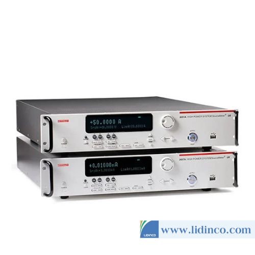
High Power SourceMeter Keithley 2657A (1fA / 100nV)
-
Voltage Source:
-
Current Source:
-
Voltage Resolution:
-
Current Resolution:
High Power SourceMeter Keithley 2657A (1fA / 100nV)
Please login to write review!