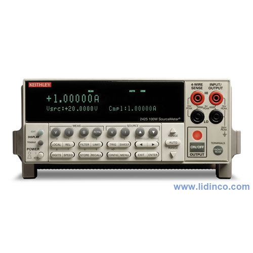
Keithley 2425 100W SourceMeter
Hotline: +84 906 988 447
Head Office: Ho Chi Minh City
- Tel: +84 2839 778 269 / 3601 6797
- Email: [email protected]
- Add: 487 Cong Hoa Street, Tan Binh Ward, Ho Chi Minh City, Vietnam
Office: Bac Ninh City
- Tel: +84 222 730 0180
- Email: [email protected]
- Add: 184 Binh Than Street, Vo Cuong Ward, Bac Ninh, Vietnam
-
 Technical Counseling
100% Free
Technical Counseling
100% Free
-
 Free Shipping
For 3.000.000vnd Order
Free Shipping
For 3.000.000vnd Order
Data is being updated

Hệ thống sourcemeter để bàn Keithley 2425 100W SourceMeter
Thông tin sản phẩm:
Keithley’s SourceMeter family are source measurement unit (SMU) instruments designed specifically for test applications that demand tightly coupled sourcing and measurement. All SourceMeter models provide precision voltage and current sourcing as well as measurement capabilities. Each SourceMeter instrument is both a highly stable DC power source and a true instrument-grade 6½-digit multimeter. The power source characteristics include low noise, precision, and readback. The multimeter capabilities include high repeatability and low noise. The result is a compact, single-channel, DC parametric tester. In operation, these instruments can act as a voltage source, a current source, a voltage meter, a current meter, and an ohmmeter. Manufacturers of components and modules for the communications, semiconductor, computer, automotive, and medical industries will find the SourceMeter instruments invaluable for a wide range of characterization and production test applications.
Advantages of a Tightly Integrated Instrument
By linking source and measurement circuitry in a single unit, these instruments offer a variety of advantages over systems configured with separate source and measurement instruments. For example, they minimize the time required for test station development, setup, and maintenance, while lowering the overall cost of system ownership. They simplify the test process itself by eliminating many of the complex synchronization and connection issues associated with using multiple instruments. And, their compact half-rack size conserves precious “real estate” in the test rack or bench.
Power of Five Instruments in One (IV Source, IVR Measure)
The tightly coupled nature of a SourceMeter instrument provides many advantages over solutions configured from separate instruments, such as a precision power supply and a digital multimeter. For example, it provides faster test times by reducing GPIB traffic and simplifies the remote programming interface. It also protects the device under test from damage due to accidental overloads, thermal runaway, etc. Both the current and voltage source are programmable with readback to help maximize device measurement integrity. If the readback reaches a programmed compliance limit, then the source is clamped at the limit, providing fault protection.
Characteristics
All SourceMeter instruments provide four-quadrant operation. In the first and third quadrants they operate as a source, delivering power to a load. In the second and fourth quadrants they operate as a sink, dissipating power internally. Voltage, current, and resistance can be measured during source or sink operation.


Automation for Speed
A SourceMeter instrument streamlines production testing. It sources voltage or current while making measurements without needing to change connections. It is designed for reliable operation in non-stop production environments. To provide the throughput demanded by production applications, the SourceMeter instrument offers many built-in features that allow it to run complex test sequences without computer control or GPIB communications slowing things down.
 |
| Linear staircase sweep |
 |
| Logarithmic staircase sweep |
 |
| Custom sweep |
Standard and Custom Sweeps
Sweep solutions greatly accelerate testing with automation hooks. Three basic sweep waveforms are provided that can be programmed for single-event or continuous operation. They are ideal for I/V, I/R, V/I, and V/R characterization.
- Linear Staircase Sweep: Moves from the start level to the stop level in equal linear steps
- Logarithmic Staircase Sweep: Done on a log scale with a specified number of steps per decade
- Custom Sweep: Allows construction of special sweeps by specifying the number of measurement points and the source level at each point
- Up to 1700 readings/second at 4½ digits to the GPIB bus
- 5000 readings can be stored in the non-volatile buffer memory
Built-In Test Sequencer (Source Memory List)
The Source Memory list provides faster and easier testing by allowing you to setup and execute up to 100 different tests that run without PC intervention.
- Stores up to 100 instrument configurations, each containing source settings, measurement settings, pass/fail criteria, etc.
- Pass/fail limit test as fast as 500µs per point
- Onboard comparator eliminates the delay caused when sending data to the computer for analysis
- Built-in, user definable math functions to calculate derived parameters
Example Test Sequence

| Test | Pass/Fail Test | If Passes Test | If Fails Test |
| Test 1 | Check V F1 at 100mA against pass/fail limits | Go to Test 2 |
|
| Test 2 | Check V F2 at 1A against pass/fail limits | Go to Test 3 | |
| Test 3 | Check leakage current at –500V and test against pass/fail limits |
|
Digital I/O Interface
The digital I/O interface can link the SourceMeter instrument to many popular component andlers, including Aetrium, Aeco, and Robotronics. Other capabilities of the interface include:
- Tight systems integration for applications such as binning and sorting
- Built-in component handler interface
- Start of test and end of test signals
- 5V, 300mA power supply
- Optional expander accessory (Model 2499-DIGIO) adds 16 digital I/O lines
Trigger Link Interface
All SourceMeter instruments include Keithley’s unique Trigger Link interface which provides high-speed, seamless communications with many of Keithley’s other instruments. For example, use the Trigger Link interface to connect a SourceMeter instrument with a Series 7000 Switching System for a complete multi-point test solution. With Trigger Link, the 7000 Series Switching Systems can be controlled by a SourceMeter instrument during a high-speed test sequence independent of a computer and GPIB.
Optional Contact Check Function
The Contact Check function makes it simple to verify good connections quickly and easily before an automated test sequence begins. This eliminates measurement errors and false product failures associated with contact fatigue, breakage, contamination, loose or broken connection, relay failures, etc. Some capabilities of this function are:
- 350µs verification and notification process time
- The output of the SourceMeter instrument is automatically shut off after a fault and is not re-activated until good contact is verified, protecting the device under test from damage and the operator from potential safety hazards
- 3 pass/fail threshold values: 2Ω, 15Ω, and 50Ω
- No energy passes through the device under test during the operation
- Enabled either from the front panel or remotely over the GPIB
- 3 fault notification methods
Unique 6-Wire Ohms Technique
SourceMeter instruments can make standard 4-wire, split Kelvin, and 6-wire, guarded ohms measurements and can be configured for either the constant current or constant voltage method. The 6-wire ohms technique:
- Uses guard and guard sense leads in addition to the 4-wire sense and source leads
- Locks out parallel current paths when measuring resistor networks or hybrid circuits to isolate the component under test
- Allows users to configure and plot data easily from Series 2400 SourceMeter instruments, making characterization of two, three, and four terminal devices a snap

6-Wire Ohms Circuit. All test current flows through
R1 because the high current guard drives the voltage across R2 to 0V.

Contact check option for 4-wire or 6-wire applications

| GENERAL SPECIFICATIONS | |||
| Noise Rejection | |||
| NPLC | NMRR | CMRR | |
| Fast | 0.01 | 80 dB | |
| Medium | 0.1 | 80 dB | |
| Slow | 1 | 60 dB | 80 dB |
| Load Impedance | Stable into 20,000pF typical | ||
| Common Mode Voltage | 250V DC (40V DC for Model 2440) | ||
| Common Mode Isolation | >10 9 Ω, <1000pF | ||
| Overrange | 105% of range, source and measure | ||
| Max. Voltage Drop Between Input/Output and sense Terminals | 5V | ||
| Max. Sense Lead Resistance | 1MΩ for rated accuracy | ||
| Sense Input Impedance | >10 Ω | ||
| Guard Offset Voltage | <150µV, typical (300µV for Models 2430, 2440) | ||
| Source Output Modes | Pulse (Model 2430 only) Fixed DC level Memory List (mixed function) Stair (linear and log) | ||
| Memory Buffer | 5,000 readings @ 5 digits (two 2,500 point buffers). Includes selected measured value(s) and time stamp. Lithium battery backup (3 yr+ battery life) | ||
| Source Memory List | 100 points max | ||
| Programmability | IEEE-488 (SCPI-1995.0), RS-232, 5 user-definable power-up states plus factory default and *RST | ||
| Digital Interface | |||
| Interlock | Active low input | ||
| Handler Interface | Start of test, end of test, 3 category bits. +5V@ 300mA supply. | ||
| Digital I/O | 1 trigger input, 4 TTL/Relay Drive outputs (33V @ 500mA, diode clamped) | ||
| Power Supply | 100V to 240V rms, 50–60Hz (automatically detected at power up). Model 2400, 2401: 190VA. Model 2410: 210VA. Model 2420: 220VA. Model 2425, 2430: 250VA. Model 2440: 240VA. | ||
| Cooling | Convection. Model 2410, 2420, 2425, 2430, 2440: Forced air, variable speed. | ||
| EMC | Conforms to European Union Directive 89/336/EEC, EN 61326-1. | ||
| Safety: UL listed to UL 61010B-1:2003 | Conforms to European Union Low Voltage Directive. | ||
| Vibration | MIL-PRF-28800F Class 3 Random | ||
| Warm-up | 1 hour to rated accuracies | ||
| Dimensions | 89mm high × 213mm wide × 370mm deep (3½ in × 8 3 / 8 in × 14 9 / 16 in). Bench Configuration (with handle and feet):104mm high × 238mm wide × 370mm deep (4 1 / 8 in × 9 3 / 8 in × 14 9 / 16 in) | ||
| Dimensions | 89mm high × 213mm wide × 370mm deep (3½ in × 8 3 / 8 in × 14 9 / 16 in). Bench Configuration (with handle and feet):104mm high × 238mm wide × 370mm deep (4 1 / 8 in × 9 3 / 8 in × 14 9 / 16 in) | ||
| Weight | 3.21kg (7.08 lbs) (Model 2425, 2430, 2440: 4.1kg, 9.0 lbs) | ||
| Environment | |||
| Operating | 0°–50°C, 70% R.H. up to 35°C. Derate 3% R.H./°C, 35°–50°C. | ||
| Storage | –25°C to 65°C | ||
| Voltage Accuracy (Local or Remote Sense) | |||||||
| Model | Range | Programming Resolution | Source Accuracy (1 Year) 23°C ±5°C ±(% rdg. + volts) | Default Measurement Resolution | Measurement Accuracy (1 Year) 23°C±5°C ±(% rdg. + volts) | Output Slew Rate (±30%) | Source/ Sink Limit |
| 2400, 2400-C, 2401 | 200.000mV | 5µV | 0.02%+600µV | 1µV | 0.012%+300µV | ±21V@ ±1.05A ±210V@ ±105mA* | |
| 2.00000V | 50µV | 0.02%+600µV | 10µV | 0.012%+300µV | |||
| 20.00000V | 500µV | 0.02%+2.4mV | 100µV | 0.015%+1.5mV | 0.08V/µs | ||
| 200.000V* | 5mV | 0.02%+24mV | 1mV | 0.015%+10mV | 0.5 V/µs | ||
| 2410, 2410-C | 200.000mV | 5µV | 0.02%+600µV | 1µV | 0.012%+300µV | ±21V@±1.05A ±1100V@±21mA | |
| 2.00000V | 50µV | 0.02%+600µV | 10µV | 0.012%+300µV | |||
| 20.0000V | 500µV | 0.02%+2.4mV | 100µV | 0.015%+1mV | 0.15V/µs | ||
| 1000.00V | 50mV | 0.02%+100mV | 10mV | 0.015%+50mV | 0.5V/µs | ||
| 2420, 2420-C | 200.000mV | 5µV | 0.02%+600 µV | 1µV | 0.012%+300µV | ±21V@±3.15A ±63V@±1.05A | |
| 2.00000V | 50µV | 0.02%+600µV | 10µV | 0.012%+300µV | |||
| 20.0000V | 500µV | 0.02%+2.4mV | 100µV | 0.015%+1mV | 0.08V/µs | ||
| 60.0000V | 1.5mV | 0.02%+7.2mV | 1mV | 0.015%+3mV | 0.14V/µs | ||
| 2425, 2425-C | 200.000mV | 5µV | 0.02%+600µV | 1µV | 0.012%+300µV | ±21V@±3.15A ±105V@±1.05A | |
| 2.00000V | 50µV | 0.02%+600µV | 10µV | 0.012%+300µV | |||
| 20.0000V | 500µV | 0.02%+2.4mV | 100µV | 0.015%+1mV | 0.08V/µs | ||
| 100.0000V | 2.5mV | 0.02%+12mV | 1mV | 0.015%+5mV | 0.25V/µs | ||
| 2430, 2430-C | 200.000mV | 5µV | 0.02%+600µV | 1µV | 0.012%+300µV | ±105V@±1.05A ±105V@±10.5A (pulse mode only) | |
| 2.00000V | 50µV | 0.02%+600µV | 10µV | 0.012%+300µV | |||
| 20.0000V | 500µV | 0.02%+2.4mV | 100µV | 0.015%+1mV | 0.08V/µs | ||
| 100.0000V | 2.5mV | 0.02%+12mV | 1mV | 0.015%+5mV | 0.25V/µs | ||
| 2440, 2440-C | 200.000mV | 5µV | 0.02%+600µV | 1µV | 0.012%+300µV | ±10.5V@±5.25A ±42V@±1.05A | |
| 2.00000V | 50µV | 0.02%+600µV | 10µV | 0.012%+300µV | |||
| 20.0000V | 500µV | 0.02%+1.2mV | 100µV | 0.015%+750µV | 0.08V/µs | ||
| 100.0000V | 5mV | 0.02%+4.8mV | 1mV | 0.015%+3mV | 0.25V/µs | ||
| *Not available on Model 2401. | |||||||
| Temperature Coefficient (0°–18°C and 28°–50°C) | ±(0.15 × accuracy specification)/°C | ||||||
| Voltage Regulation | |||||||
| Line | 0.01% of range | ||||||
| Load | 0.01% of range + 100µV | ||||||
| Over Voltage Protection | User selectable values, 5% tolerance. Factory default = none | ||||||
| Current Limit | Bipolar current limit (compliance) set with single value. Min. 0.1% of range | ||||||
| Overshoot | <0.1% typical (full scale step, resistive load, 10mA range). | ||||||
| ADDITIONAL SOURCE SPECIFICATIONS (All Models) | |||||||
| Transient Response Time | 30µs minimum for the output to recover to its spec. following a step change in load | ||||||
| Command Processing Time | Maximum time required for the output to begin to change following the receipt of :SOURce:VOLTage|CURRent < nrf > command. | ||||||
| Autorange On | 10ms. | ||||||
| Autorange Off | 7ms. | ||||||
| Output Settling Time | Time required to reach 0.1% of final value after command is processed. 100µs typical. Resistive load. 10µA to 100mA range | ||||||
| DC Floating Voltage | Output can be floated up to ±250VDC (Model 2440 ±40VDC) from chassis ground | ||||||
| Remote Sense | Up to 1V drop per load lead | ||||||
| ADDITIONAL PULSE MODE SOURCE SPECIFICATIONS (2430 and 2430-C only) | |||||||
| Maximum Duty Cycle | 8%, hardware limited, 10A range only. All other ranges 100% | ||||||
| Maximum Pulse Width | 5ms from 90% rising to 90% falling edge, 2.5ms 10A range | ||||||
| Minimum Pulse Width | 150µs | ||||||
| Minimum Pulse Resolution | 50µs typical, 70µs max., limited by system jitter | ||||||
| Source Accuracy | Determined by settling time and source range specifications | ||||||
| Output Settling Time 0.1% | 800µs typ., source I = 10A into 10Ω, limited by voltage slew rate. 500µs typ., source I = 10A into 1Ω, limited by voltage slew rate. | ||||||
| Output Slew Rate | |||||||
| Voltage (10Ω load) | 0.25V/µs ±30% on 100V range. 0.08V/µs ±30% on 20V range, 10A range | ||||||
| Current (0Ω load) | 0.25V/µs ±30% on 100V range. 0.08V/µs ±30% on 20V range, 10A range | ||||||
| NOTES | |||||||
|
|||||||
| Current Accuracy (Local or Remote Sense) | ||||||||||||||||||
| Model | Range | Programming Resolution | Source Accuracy (1 Year) 23°C ±5°C ±(% rdg. + volts) | Default Measurement Resolution | Measurement Accuracy (1 Year) 23°C±5°C ±(% rdg. + volts) | Source/ Sink Limit | ||||||||||||
| 2400, 2400-C, 2401 | 1.00000µA | 50pA | 0.035%+600pA | 10pA | 0.029%+300pA | ±1.05A@±21V ±105mA@±210V | ||||||||||||
| 10.0000µA | 500pA | 0.033%+2nA | 100pA | 0.027%+700pA | ||||||||||||||
| 100.000µA | 5nA | 0.031%+20nA | 1nA | 0.025%+6nA | ||||||||||||||
| 1.00000mA | 50nA | 0.034%+200nA | 10nA | 0.027%+60nA | ||||||||||||||
| 10.00000mA | 500nA | 0.045%+2µA | 100nA | 0.035%+600nA | ||||||||||||||
| 100.00000mA | 5µA | 0.066%+20µA | 1µA | 0.055%+6µA | ||||||||||||||
| 1.00000A2 | 50µA | 0.27%+900µA | 10µA | 0.22%+570µA | ||||||||||||||
| 2410, 2410-C | 1.00000µA | 50pA | 0.035%+600pA | 10pA | 0.029%+300pA | ±1.05A@±21V ±21mA@±1100V | ||||||||||||
| 10.0000µA | 500pA | 0.033%+2nA | 100pA | 0.027%+700pA | ||||||||||||||
| 100.000µA | 5nA | 0.031%+20nA | 1nA | 0.025%+6nA | ||||||||||||||
| 1.00000mA | 50nA | 0.034%+200nA | 10nA | 0.027%+60nA | ||||||||||||||
| 20.0000mA | 500nA | 0.045%+4µA | 100nA | 0.035%+1.2µA | ||||||||||||||
| 100.00000mA | 5µA | 0.066%+20µA | 1µA | 0.055%+6µA | ||||||||||||||
| 1.00000A2 | 50µA | 0.27%+900µA | 10µA | 0.22%+570µA | ||||||||||||||
| 2420, 2420-C | 10.0000µA | 500pA | 0.033%+2nA | 100pA | 0.027%+700pA | ±3.15A@±21V ±1.05A@±63V | ||||||||||||
| 100.000µA | 5nA | 0.031%+20nA | 1nA | 0.025%+6nA | ||||||||||||||
| 1.00000mA | 50nA | 0.034%+200nA | 10nA | 0.027%+60nA | ||||||||||||||
| 10.0000mA | 500nA | 0.045%+2µA | 100nA | 0.035%+600nA | ||||||||||||||
| 100.000mA | 5µA | 0.066%+20µA | 1µA | 0.055%+6µA | ||||||||||||||
| 1.00000A2 | 50µA | 0.067%+900µA | 10µA | 0.066%+570µA | ||||||||||||||
| 3.00000A2 | 50µA | 0.059%+2.7mA | 10µA | 0.052%+1.71mA | ||||||||||||||
| 2425, 2425-C | 10.0000µA | 500pA | 0.033%+2nA | 100pA | 0.027%+700pA | ±3.15A@±21V ±1.05A@±105V | ||||||||||||
| 100.000µA | 5nA | 0.031%+20nA | 1nA | 0.025%+6nA | ||||||||||||||
| 1.00000mA | 50nA | 0.034%+200nA | 10nA | 0.027%+60nA | ||||||||||||||
| 10.0000mA | 500nA | 0.045%+2µA | 100nA | 0.035%+600nA | ||||||||||||||
| 100.000mA | 5µA | 0.066%+20µA | 1µA | 0.055%+6µA | ||||||||||||||
| 1.00000A2 | 50µA | 0.067%+900µA | 10µA | 0.066%+570µA | ||||||||||||||
| 3.00000A2 | 50µA | 0.059%+2.8mA | 10µA | 0.052%+1.71mA | ||||||||||||||
| 2430, 2430-C | 10.0000µA | 500pA | 0.033%+2nA | 100pA | 0.027%+700pA | ±1.05A@±105V ±10.5A@±105V (pulse mode only) | ||||||||||||
| 100.000µA | 5nA | 0.031%+20nA | 1nA | 0.025%+6nA | ||||||||||||||
| 1.00000mA | 50nA | 0.034%+200nA | 10nA | 0.027%+60nA | ||||||||||||||
| 10.0000mA | 500nA | 0.045%+2µA | 100nA | 0.035%+600nA | ||||||||||||||
| 100.000mA | 5µA | 0.066%+20µA | 1µA | 0.055%+6µA | ||||||||||||||
| 1.00000A2 | 50µA | 0.067%+900µA | 10µA | 0.066%+570µA | ||||||||||||||
| 3.00000A2 | 500µA | 0.059%+2.8mA | 10µA | 0.052%+1.71mA | ||||||||||||||
| 10.00000A4 | 500µA | 0.089%+5.9mA | 10µA | 0.082%+1.71mA | ||||||||||||||
| 2440, 2440-C | 10.0000µA | 500pA | 0.033%+2nA | 100pA | 0.027%+700pA | ±5.25A@±10.5V ±1.05A@±42V | ||||||||||||
| 100.000µA | 5nA | 0.031%+20nA | 1nA | 0.025%+6nA | ||||||||||||||
| 1.00000mA | 50nA | 0.034%+200nA | 10nA | 0.027%+60nA | ||||||||||||||
| 10.0000mA | 500nA | 0.045%+2µA | 100nA | 0.035%+600nA | ||||||||||||||
| 100.000mA | 5µA | 0.066%+20µA | 1µA | 0.055%+6µA | ||||||||||||||
| 1.00000A | 50µA | 0.067%+900µA | 10µA | 0.066%+570µA | ||||||||||||||
| 5.00000A | 50µA | 0.10%+5.4mA | 10µA | 0.10%+3.42mA | ||||||||||||||
| Temperature Coefficient (0°–18°C and 28°–50°C) | ±(0.15 × accuracy specification)/°C | |||||||||||||||||
| Current RegulatioN | ||||||||||||||||||
| Line | 0.01% of range | |||||||||||||||||
| Load | 0.01% of range (except Model 2440 5A range 0.05%) + 100pA | |||||||||||||||||
| Voltage Limit | Bipolar voltage limit (compliance) set with single value. Min. 0.1% of range | |||||||||||||||||
| Overshoot | <0.1% typical (1mA step, RL = 10kO, 20V range for Model 2400, 2401, 2410, 2420, 2425, 2430), (10V range for Model 2440) | |||||||||||||||||
| CONTACT CHECK SPECIFICATIONS (requires -C version) | ||||||||||||||||||
| (Not available for Model 2401) | ||||||||||||||||||
| Speed | 350µs for verification and notification | |||||||||||||||||
| Contact Check | ||||||||||||||||||
|
||||||||||||||||||
| NOTES |
|
|||||||||||||||||
| Resistance Measurement Accuracy (Local or Remote Sense) | |||
| Range | Default Resolution | Default Test Current 2400, 2401, 2410 | Default Test Current 2420, 2425, 2430, 2440 |
| <0.20000 Ω | |||
| 2.00000Ω | 10µΩ | 1A | |
| 20.0000Ω | 100µΩ | 100 mA | 100 mA |
| 200.000Ω | 1mΩ | 10 mA | 10 mA |
| 2.00000kΩ | 10mΩ | 1 mA | 1 mA |
| 20.0000kΩ | 100mΩ | 100µA | 100µA |
| 200.000kΩ | 1Ω | 10µA | 10µA |
| 2.00000 MΩ | 10Ω | 1 µA | 1 µA |
| 20.0000 MΩ | 100Ω | 1 µA | 1 µA |
| 200.000 MΩ | 1kΩ | 100 nA | |
| >200.000 MΩ | |||
| Resistance Measurement Accuracy (Local or Remote Sense) | |||
| Normal Accuracy (23°C ±5°C) 1 Year, ±(% rdg. + ohms) | Enhanced Accuracy (23°C ±5°C) 4 1 Year, ±(% rdg. + ohms) | ||
| 2400, 2401 | 2410 | 2420, 2425 2430, 2440 | 2400, 2401 |
| Source I ACC + Meas. V ACC | |||
| Source I ACC + Meas V ACC | 0.17% + 0.0003 Ω | Source I ACC + Meas V ACC | |
| 0.10% + 0.003 Ω | 0.11% + 0.006 Ω | 0.10% + 0.003 Ω | 0.07% + 0.001 Ω |
| 0.08% + 0.03 Ω | 0.09% + 0.1 Ω | 0.08% + 0.03 Ω | 0.05% + 0.01 Ω |
| 0.07% + 0.3 Ω | 0.08% + 0.6 Ω | 0.07% + 0.3Ω | 0.05% + 0.1 Ω |
| 0.06% +3 Ω | 0.07% + 6 Ω | 0.06% + 3 Ω | 0.04% + 1Ω |
| 0.07% + 30 Ω | 0.07% + 60 Ω | 0.07% + 30 Ω | 0.05% + 10 Ω |
| 0.11% + 300 Ω | 0.12% + 600Ω | 0.11% + 300 Ω | 0.05% + 100Ω |
| 0.11% + 1 kΩ | 0.12% + 2.4 kΩ | 0.11% + 1 kΩ | 0.05% + 500 Ω |
| 0.66% + 10 kΩ | 0.66% + 24 kΩ | Source I ACC + Meas. V ACC | 0.35% + 5 kΩ |
| Source I ACC + Meas. V ACC | |||
| Temperature Coefficient (0°–18°C and 28°–50°C) | ±(0.15 × accuracy specification)/°C | ||
| Source I Mode, Manual OHMS | Total uncertainty = I source accuracy + V measure accuracy (4-wire remote sense) | ||
| Source V Mode, Manual OHMS | Total uncertainty = V source accuracy + I measure accuracy (4-wire remote sense) | ||
| 6-Wire OHMS Mode | Available using active ohms guard and guard sense. Max. Guard Output Current: 50mA (except 1A range). Accuracy is load dependent. Refer to White Paper no. 2033 for calculation formula | ||
| Guard Output Impedance | <0.1O in ohms mode | ||
| NOTES |
|
||
Accessories


-
Voltage Source:
-
Current Source:
-
Voltage Resolution:
-
Current Resolution:
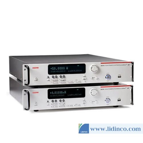
High Power SourceMeter Keithley 2657A (1fA / 100nV)
-
Voltage Source:
-
Current Source:
-
Voltage Resolution:
-
Current Resolution:
High Power SourceMeter Keithley 2657A (1fA / 100nV)
Please login to write review!