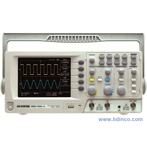
Digital Oscilloscope GW Instek GDS-1052-U, 50MHz, 02 channel
Hotline: +84 906 988 447
Head Office: Ho Chi Minh City
- Tel: +84 2839 778 269 / 3601 6797
- Email: sales@lidinco.com
- Add: 487 Cong Hoa Street, Tan Binh Ward, Ho Chi Minh City, Vietnam
Office: Bac Ninh City
- Tel: +84 222 730 0180
- Email: bn@lidinco.com
- Add: 184 Binh Than Street, Vo Cuong Ward, Bac Ninh, Vietnam
-
 Technical Counseling
100% Free
-
 Free Shipping
For 3.000.000vnd Order
Data is being updated
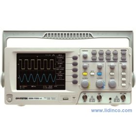
Máy hiện sóng GW Instek GDS-1052-U băng thông 50 MHz, lấy mẫu 250 MSa/s, 2 kênh, bộ nhớ 4 kpts/kênh, màn hình 5.7 inch.
The GDS-1000-U Series offers 100MHz, 70MHz and 50MHz digital storage oscilloscopes with 5.7" color TFT LCD displays. With dual sampling modes, a 4,000 point record length, a real-time sampling rate of 250MSa/s and an ET sampling rate of 25GSa/s, the GDS-1000-U Series DSO provides an excellent balance of performance between memory length and sampling speed. Other major features include user-friendly menu tree operations, compact size, ergonomic design, USB host for PC connectivity and USB device port support. The GDS-1000-U Series is designed to meet today's most demanding engineering requirements and budgets.
USB Interface & Data Logger
The USB Host port on the front significantly enhance the data storage capability of the product. The large amount of data, including screenshot, waveform and panel setup, could be easily stored into a popular flash disk. A USB device port on the rear of the product transfers the screen image and waveform raw data to PC — and also allows your PC to remotely control the GDS-1052-U DSO.
Waveform Saving & Automatic Measurement
A total of 15 waveforms can be saved into memory to be displayed at a later time. Two saved reference waveforms and two live waveforms can be compared on the screen at the same time. All signal time and voltage related measurements can be shown on the screen simultaneously in real-time via the Measure key press.
Enhanced Calibration Signal Output
The GDS-1052-U has an enhanced 1kHz calibration signal. Its output frequency is adjustable from 1 kHz to 100 kHz and has an adjustable duty cycle of 5% to 95%. Due to the flexible output, the calibration output can also be used as a basic signal generator for other applications.
Autoset Disable Function
For educational purposes, instructors might not want to use the Autoset function on the DSO when they are teaching how to use oscilloscopes. On the GDS-1000-U Series, the Autoset function can be disabled, allowing students to manually operate the oscilloscope functions to further enrich their learning experience.
Go/NoGo Function
Go/NoGo testing function check whether the incoming signal violates the user-defined template. Users can easily define this template by setting the tolerance ratio to determine violation conditions. Go/NoGo testing can either keep counting violation number or stop testing when violation conditions are met.
Freewave PC Software
Freewave DSO remote control and monitoring software is fully supported for the GDS-1052-U series DSOs and is available free of charge from the GW Instek website. Freewave lets you remotely monitor the DSO, capture waveform data or even capture screenshots. Via a USB connection, Freewave is able to provide near-realtime monitoring and control. Flexible saving options allow you to capture data for later analysis and observation. Screen images can be captured to bitmap or jpeg formats. Waveform data can be saved to CSV for spreadsheet manipulation or computer analysis. Waveforms can also be saved as AVI movies to observe signal variation over time.
| VERTICAL | ||
| Channels | 2 | |
| Bandwidth | DC ~ 50MHz (-3dB) | |
| Rise Time | <7ns Approx. | |
| Sensitivity | 2mV/div ~ 10V/div (1-2-5 increments) | |
| Accuracy | ±(3% x |Readout|+0.1 div + 1mV) | |
| Input Coupling | AC, DC & Ground | |
| Input Impedance | 1M±2%, ~15pF | |
| Polarity | Normal & Invert | |
| Maximum Input | 300V (DC+AC peak), CATII | |
| Waveform Signal Process | + , - , FFT | |
| Offset Range | 2mV/div ~ 50mV/div : ±0.4V , 10mV/div ~ 500mV/div : ±4V 1V/div ~ 5V/div : ±40V , 10V/div:±300V | |
| Bandwidth Limit | 20MHz (-3dB) | |
| TRIGGER | ||
| Sources | CH1 , CH2 , Line , EXT | |
| Modes | Auto, Normal, Single, TV, Edge, Pulse Width | |
| Coupling | AC , DC , LF rej. , HF rej. , Noise rej. | |
| Sensitivity | DC ~ 25MHz : Approx. 0.5div or 5mV 25MHz ~50/70/ 100MHz: Approx. 1.5div or 15mV | |
| EXT TRIGGER | ||
| Range | ±15V | |
| Sensitivity | DC ~ 25MHz : ~ 50mV ; 25M ~ 50/70/100MHz : ~15mV | |
| Input Impedance | 1MΩ±2% , ~ 16pF | |
| Maximum Input | 300V (DC AC peak) , CATII | |
| HORIZONTAL | ||
| Range | 1ns/div ~ 10s/div (1-2.5-5 increments); ROLL : 50ms/div ~ 50s/div | |
| Modes | Main, Window, Window Zoom, Roll, X-Y | |
| Accuracy | ±0.01% | |
| Pre-Trigger | 10 div maximum | |
| Post-Trigger | 1000 div | |
| X-Y MODE | ||
| X-Axis Input | Channel 1 | |
| Y-Axis Input | Channel 2 | |
| Phase Shift | ±3° at 100kHz | |
| SIGNAL ACQUISITION | ||
| Real-Time Sample Rate | 250MSa/s maximum | |
| Equivalent Sample Rate | 25GSa/s maximum | |
| Vertical Resolution | 8 Bits | |
| Record Length | 4K Dots maximum | |
| Acquisition Mode | Normal, Peak Detect, Average | |
| Peak Detection | 10ns (500ns/div ~ 10s/div) | |
| Average | 2 , 4 , 8 , 16 , 32 , 64 , 128 , 256 | |
| CURSORS AND MEASUREMENT | ||
| Voltage Measurement | Vpp , Vamp , V avg , Vrms , Vhi , Vlo , Vmax , Vmin , Rise Preshoot/Overshoot , Fall Preshoot/Overshoot | |
| Time Measurement | Freq , Period , Rise Time , Fall Time , Positive Width , Negative Width , Duty Cycle | |
| Cursors Measurement | Voltage difference between cursors (ΔV) Time difference between cursors (ΔT) | |
| Auto Counter | Resolution : 6 digits Accuracy : ±2% Signal Source: All available trigger source except the Video trigger mode | |
| CONTROL PANEL FUNCTION | ||
| Autoset | Automatically adjusts Vertical VOLTS/DIV, Horizontal TIME/DIV, and Trigger level | |
| Save Setup | Up to 15 sets of measurement conditions | |
| Save Waveform | 15 sets of waveform | |
| DISPLAY | ||
| TFT LCD Type | 5.7 inch | |
| Display Resolution | 234 (Vertically) x 320 (Horizontally) Dots | |
| Display Graticule | 8 x 10 divisions | |
| Display Brightness | Adjustable | |
| INTERFACE | ||
| USB Slave Connector | USB1.1 & 2.0 full speed compatible (printers and flash disk not supported) | |
| USB Host | Image (BMP), waveform data (CSV), and setup (SET) | |
| POWER SOURCE | ||
| Line Voltage Range | AC 100V ~ 240V , 48Hz ~ 63Hz , Auto selection | |
| MISCELLANEOUS | ||
| Multi-Language Menu | Available | |
| Online Help | Available | |
| Go/NoGo Function | Available | |
| Data Logger | Available | |
| DIMENSIONS & WEIGHT | ||
| 310(W) x 142(H) x 140(D)mm; Approx. 2.5kg | ||
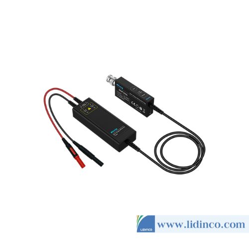
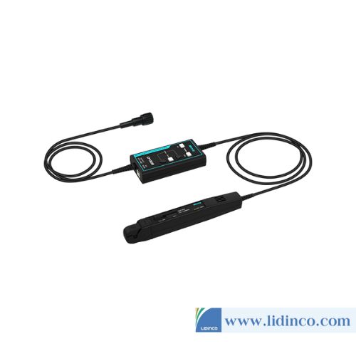
Accessory: User manual x 1, Power Cord x 1 Probe-GTP-070A-4 : 70MHz ( 10 : 1/1 :1 ) Switchable Passive Probe for GDS-1052-U (one per channel) Probe-GTP-070A-2 : 70MHz ( 10 : 1/1 :1 ) Switchable Passive Probe for GDS-1072-U (one per channel) Probe-GTP-100A-2 : 100MHz ( 10 : 1/1 :1 ) Switchable Passive Probe for GDS-1102-U (one per channel) Optional Accessories GSC-006 Soft carrying case GTL-110 Test lead, BNC-BNC heads GTL-242 USB 2.0 A-B type cable
Accessories

-
Bandwidth:
-
Sampling Rate:
-
Waveform Length:
-
Channels:
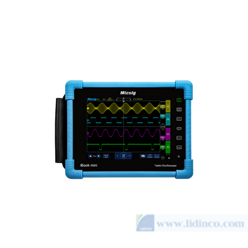
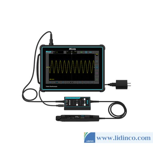
Micsig TO1152 150MHz Tablet Oscilloscope

-
Current Range:
-
Voltage Range:
-
Display Resolution:
-
Accuracy:
Dual Measurement Multimeter GW Instek GDM-8352
Please login to write review!

