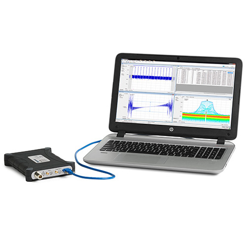
Spectrum analyzer Tekronix RSA306 USB, 9KHz ~ 6.2GHz
Hotline: +84 906 988 447
Head Office: Ho Chi Minh City
- Tel: +84 2839 778 269 / 3601 6797
- Email: sales@lidinco.com
- Add: 487 Cong Hoa Street, Ward 15, Tan Binh Dist, HCM City, Vietnam
Office: Bac Ninh City
- Tel: +84 222 730 0180
- Email: bn@lidinco.com
- Add: 184 Binh Than Street, Vo Cuong Ward, Bac Ninh City, Vietnam
-
 Technical Counseling
100% Free
Technical Counseling
100% Free
-
 Free Shipping
For 3.000.000vnd Order
Free Shipping
For 3.000.000vnd Order
Specification
Data is being updated
Description
The RSA306B USB spectrum / signal analyzer might be small but it packs a big punch. It’s loaded with features you’d expect from spectrum analyzers twice the size and twice the price. Perfect for everyday tasks
Key performance specifications
- 9 kHz to 6.2 GHz frequency range covers a broad range of analysis needs
- +20 dBm to -160 dBm measurement range
- Captures interference to ensure that you see problems first time, every time
- Mil-Std 28800 Class 2 environmental, shock and vibration specifications for use in harsh conditions
Key features
- Full-featured spectrum analysis capability with included Tektronix SignalVu-PC™ software
- 27 spectrum and signal analysis measurements standard
- Options for mapping, modulation analysis, standards support, pulse measurements, and frequency settling
- Real time Spectrum/Spectrogram display to minimize time spent on transient and interference hunting
- Application programming interface (API) included for Microsoft Windows environments
- MATLAB instrument driver for use with Instrument Control Toolbox
- Streaming capture records long-term events
Applications
- Academic/education
- Maintenance, installation and repair in the factory or field
- Value-conscious design and manufacturing
- Interference hunting
| Tektronix RSA306 Specifications | |||||||||||||||||||||||||||||||||||||||||||
Specifications are valid within the following conditions:
| |||||||||||||||||||||||||||||||||||||||||||
| Frequency | |||||||||||||||||||||||||||||||||||||||||||
| RF input frequency range | 9 kHz to 6.2 GHz | ||||||||||||||||||||||||||||||||||||||||||
| Frequency | |||||||||||||||||||||||||||||||||||||||||||
Initial | ±3 ppm + aging (18 °C to 28 °C ambient, after 20 minute warm up) ±25 ppm + aging (-10 °C to 55 °C ambient, after 20 minute warm up), typical | ||||||||||||||||||||||||||||||||||||||||||
Aging (typical) | ±3 ppm (1st year), ±1 ppm/year thereafter | ||||||||||||||||||||||||||||||||||||||||||
| External frequency reference input | |||||||||||||||||||||||||||||||||||||||||||
Input frequency range | 10 MHz ±10 Hz | ||||||||||||||||||||||||||||||||||||||||||
Input level range | -10 dBm to +10 dBm sinusoid | ||||||||||||||||||||||||||||||||||||||||||
Impedance | 50 Ω | ||||||||||||||||||||||||||||||||||||||||||
| Center frequency resolution | |||||||||||||||||||||||||||||||||||||||||||
Block IQ samples | 1 Hz | ||||||||||||||||||||||||||||||||||||||||||
Streamed ADC samples | 500 kHz | ||||||||||||||||||||||||||||||||||||||||||
| Amplitude | |||||||||||||||||||||||||||||||||||||||||||
| RF input impedance | 50 Ω | ||||||||||||||||||||||||||||||||||||||||||
| RF input VSWR (typical) | ≤ 1.8:1 (10 MHz to 6200 MHz, reference level ≥ +10 dBm) | ||||||||||||||||||||||||||||||||||||||||||
| Maximum RF input level without damage | |||||||||||||||||||||||||||||||||||||||||||
DC voltage | ±40 V DC | ||||||||||||||||||||||||||||||||||||||||||
Reference level ≥ –10 dBm | +23 dBm (continuous or peak) | ||||||||||||||||||||||||||||||||||||||||||
Reference level < –10 dBm | +15 dBm (continuous or peak) | ||||||||||||||||||||||||||||||||||||||||||
| Maximum RF input operating level | The maximum level at the RF input for which the instrument will meet its measurement specifications. | ||||||||||||||||||||||||||||||||||||||||||
Center frequency < 22 MHz (low-frequency path) | +15 dBm | ||||||||||||||||||||||||||||||||||||||||||
Center frequency ≥22 MHz (RF path) | +20 dBm | ||||||||||||||||||||||||||||||||||||||||||
| Amplitude accuracy at all center frequencies |
| ||||||||||||||||||||||||||||||||||||||||||
| Intermediate frequency and acquisition system | |||||||||||||||||||||||||||||||||||||||||||
| IF bandwidth | 40 MHz | ||||||||||||||||||||||||||||||||||||||||||
| ADC sample rate and bit width | 112 Ms/s, 14 bits | ||||||||||||||||||||||||||||||||||||||||||
| Real-time IF acquisition data (uncorrected) | 112 Ms/s, 16-bit integer real samples 40 MHz BW, 28 ±0.25 MHz Digital IF, uncorrected. Corrected values are stored with saved files Block streaming data at an average rate of 224 MB/s | ||||||||||||||||||||||||||||||||||||||||||
| Block baseband acquisition data (corrected) | |||||||||||||||||||||||||||||||||||||||||||
Maximum acquisition time | 1 second | ||||||||||||||||||||||||||||||||||||||||||
Bandwidths | ≤ 40 /( 2 N ) MHz, 0 Hz Digital IF, N ≥ 0 | ||||||||||||||||||||||||||||||||||||||||||
Sample rates | ≤ 56 / (2 N ) Msps, 32-bit float complex samples, N ≥ 0 | ||||||||||||||||||||||||||||||||||||||||||
| Channel amplitude flatness | ±1.0 dB, 18 °C to 28 °C ±2.0 dB, -10 °C to 55 °C, typical Reference level +10 dBm to -30 dBm, alignment run before testing Applies to corrected IQ data, with signal to noise ratios > 40 dB | ||||||||||||||||||||||||||||||||||||||||||
| Trigger | |||||||||||||||||||||||||||||||||||||||||||
| Trigger/sync input | |||||||||||||||||||||||||||||||||||||||||||
Voltage range | TTL, 0.0 V – 5.0 V | ||||||||||||||||||||||||||||||||||||||||||
Trigger level, positive-going threshold voltage | 1.6 V minimum; 2.1 V maximum | ||||||||||||||||||||||||||||||||||||||||||
Trigger level, negative-going threshold voltage | 1.0 V minimum; 1.35 V maximum | ||||||||||||||||||||||||||||||||||||||||||
Impedance | 10 kΩ | ||||||||||||||||||||||||||||||||||||||||||
| IF power trigger | |||||||||||||||||||||||||||||||||||||||||||
Threshold range | 0 dB to -50 dB from reference level, for trigger levels > 30 dB above the noise floor | ||||||||||||||||||||||||||||||||||||||||||
Type | Rising or falling edge | ||||||||||||||||||||||||||||||||||||||||||
Trigger re-arm time | ≤100 μs | ||||||||||||||||||||||||||||||||||||||||||
| Noise and distortion | |||||||||||||||||||||||||||||||||||||||||||
| Displayed Average Noise Level (DANL) |
| ||||||||||||||||||||||||||||||||||||||||||
| Phase noise |
| ||||||||||||||||||||||||||||||||||||||||||
| Residual spurious response | < -85 dBm (Reference level ≤ -50 dBm, RF input terminated with 50 Ω) Exceptions: < -78 dBm: Harmonics of 112 MHz in the range 1680-2688 MHz; 4750, 4905-4965 MHz | ||||||||||||||||||||||||||||||||||||||||||
| Input related spurious response (SFDR) | ≤ -50 dBc, 18 °C to 28 °C, with auto settings on and signals 10 dB below reference level of -30 dBm ≤ -50 dBc, -10 °C to 55 °C, typical, with auto settings on and signals 10 dB below reference level, reference level -30 dBm) Exceptions, typical: IF feedthrough: ≤ -30 dBc for 2340 MHz - 2420 MHz Image: ≤ -30 dBc for 4570 MHz - 4760 MHz; ≤ -45 dBc for 2860 MHz - 3460 MHz RFx2LO: ≤ -40 dBc for 1850-1960, 3700-4000 MHz; -45 dBc for 3890 – 3910 MHz 2RFx2LO: ≤ -45 dBc for 2140, 4270 MHz | ||||||||||||||||||||||||||||||||||||||||||
| Residual FM | < 10 Hz P-P (95% confidence) | ||||||||||||||||||||||||||||||||||||||||||
| Noise and distortion | |||||||||||||||||||||||||||||||||||||||||||
| 3 RD order IM distortion | Two input CW signals, 1 MHz separation, each input signal level 5 dB below the reference level setting at the RF input Reference level at-15 dBm disables Preamp; reference level at -30 dBm enables Preamp | ||||||||||||||||||||||||||||||||||||||||||
Center frequency 2130 MHz | ≤ -60 dBc at reference level -15 dBm, 18 °C to 28 °C ≤ -60 dBc, at reference level -15 dBm, -10 °C to 55 °C, typical | ||||||||||||||||||||||||||||||||||||||||||
40 MHz to 6.2 GHz, typical | < -58 dBc at reference level = -10 dBm < -50 dBc at reference level = -50 dBm | ||||||||||||||||||||||||||||||||||||||||||
| 3 RD order intercept (TOI) | |||||||||||||||||||||||||||||||||||||||||||
Center frequency 2130 MHz | ≥ +10 dBm at reference level -15 dBm, 18 °C to 28 °C ≥ +10 dBm, at reference level -15 dBm, -10 °C to 55 °C, typical | ||||||||||||||||||||||||||||||||||||||||||
40 MHz to 6.2 GHz, typical | +14 dBm at reference level -10 dBm -30 dBm at reference level -50 dBm | ||||||||||||||||||||||||||||||||||||||||||
| 2ND harmonic distortion, typical | < -55 dBc, 10 MHz to 300 MHz, reference level = 0 dBm < -60 dBc, 300 MHz to 3.1 GHz, reference level = 0 dBm < -50 dBc, 10 MHz to 3.1 GHz, reference level = -40 dBm Exception: < -45 dBc in the range 1850-2330 MHz | ||||||||||||||||||||||||||||||||||||||||||
| 2ND harmonic intercept (SHI) | +55 dBm, 10 MHz to 300 MHz, reference level = 0 dBm +60 dBm, 300 MHz to 3.1 GHz, reference level = 0 dBm +10 dBm, 10 MHz to 3.1 GHz, reference level = -40 dBm Exception: < +5 dBm in the range 1850-2330 MHz | ||||||||||||||||||||||||||||||||||||||||||
| Local oscillator feedthrough to input connector | < -75 dBm at reference level = -30 dBm | ||||||||||||||||||||||||||||||||||||||||||
| Audio Output | |||||||||||||||||||||||||||||||||||||||||||
| Audio output (from SignalVu-PC or application programming interface) | |||||||||||||||||||||||||||||||||||||||||||
Types | AM, FM | ||||||||||||||||||||||||||||||||||||||||||
IF bandwidth range | Five selections, 8 kHz – 200 kHz | ||||||||||||||||||||||||||||||||||||||||||
Audio output frequency range | 50 Hz – 10 kHz | ||||||||||||||||||||||||||||||||||||||||||
PC audio output | 16 bits at 32 ks/s | ||||||||||||||||||||||||||||||||||||||||||
Audio file output format | .wav format, 16 bit, 32 ks/s | ||||||||||||||||||||||||||||||||||||||||||
| SignalVu-PC base performance summary Selected SignalVu-PC features when used with the RSA306. See the SignalVu-PC datasheet for more information on the application features. | |||||||||||||||||||||||||||||||||||||||||||
| SignalVu-PC/RSA306 key characteristics | |||||||||||||||||||||||||||||||||||||||||||
Maximum span | 40 MHz real-time 9 kHz - 6.2 GHz swept | ||||||||||||||||||||||||||||||||||||||||||
Maximum acquisition time | 1.0 s | ||||||||||||||||||||||||||||||||||||||||||
Minimum IQ resolution | 17.9 ns (acquisition BW = 40 MHz) | ||||||||||||||||||||||||||||||||||||||||||
| Spectrum display | |||||||||||||||||||||||||||||||||||||||||||
Traces | Three traces + 1 math trace + 1 trace from spectrogram for spectrum display | ||||||||||||||||||||||||||||||||||||||||||
Trace functions | Normal, Average (VRMS), Max Hold, Min Hold, Average of Logs | ||||||||||||||||||||||||||||||||||||||||||
Detector | Average (VRMS), Average, CISPR peak, +Peak, -Peak, Sample | ||||||||||||||||||||||||||||||||||||||||||
Spectrum trace length | 801, 2401, 4001, 8001,10401, 16001, 32001, and 64001 points | ||||||||||||||||||||||||||||||||||||||||||
RBW range | 10 Hz to 10 MHz | ||||||||||||||||||||||||||||||||||||||||||
| DPX spectrum display | |||||||||||||||||||||||||||||||||||||||||||
Spectrum processing rate (RBW = auto, trace length 801) | 10,000/s | ||||||||||||||||||||||||||||||||||||||||||
DPX bitmap resolution | 201x801 | ||||||||||||||||||||||||||||||||||||||||||
Marker information | Amplitude, frequency, signal density | ||||||||||||||||||||||||||||||||||||||||||
Minimum signal duration for 100% probability of detection | 100 μs Span: 40 MHz, RBW = Auto, Max-hold on Due to the non-deterministic execution time of programs running under the Microsoft Windows OS, this specification may not be met when the host PC is heavily loaded with other processing tasks | ||||||||||||||||||||||||||||||||||||||||||
Span range (continuous processing) | 1 kHz to 40 MHz | ||||||||||||||||||||||||||||||||||||||||||
Span range (swept) | Up to maximum frequency range of instrument | ||||||||||||||||||||||||||||||||||||||||||
Dwell time per step | 50 ms to 100 s | ||||||||||||||||||||||||||||||||||||||||||
Trace processing | Color-graded bitmap, +Peak, -Peak, average | ||||||||||||||||||||||||||||||||||||||||||
Trace length | 801, 2401, 4001, 10401 | ||||||||||||||||||||||||||||||||||||||||||
RBW range | 1 kHz to 10 MHz | ||||||||||||||||||||||||||||||||||||||||||
| DPX Spectrogram display | |||||||||||||||||||||||||||||||||||||||||||
Trace detection | +Peak, -Peak, Average(V RMS ) | ||||||||||||||||||||||||||||||||||||||||||
Trace length, memory depth | 801 (60,000 traces) 2401 (20,000 traces) 4001 (12,000 traces) | ||||||||||||||||||||||||||||||||||||||||||
Time resolution per line | 50 ms to 6400 s, user selectable | ||||||||||||||||||||||||||||||||||||||||||
| SignalVu-PC base performance summary | |||||||||||||||||||||||||||||||||||||||||||
| Analog modulation analysis (standard) | |||||||||||||||||||||||||||||||||||||||||||
AM demodulation accuracy, typical | ±2% 0 dBm input at center, carrier frequency 1 GHz, 1kHz/5kHz input/modulated frequency, 10% to 60% modulation depth 0 dBm input power level, reference level = 10 dBm | ||||||||||||||||||||||||||||||||||||||||||
FM demodulation accuracy, typical | ±3% 0 dBm input at center, carrier frequency 1 GHz, 400Hz/1kHz input/modulated frequency 0 dBm input power level, reference level = 10 dBm | ||||||||||||||||||||||||||||||||||||||||||
PM demodulation accuracy, typical | ±1% of measurement bandwidth 0 dBm input at center, carrier frequency 1 GHz, 1kHz/5kHz input/modulated frequency 0 dBm input power level, reference level = 10 dBm | ||||||||||||||||||||||||||||||||||||||||||
| SignalVu-PC options | |||||||||||||||||||||||||||||||||||||||||||
| AM/FM/PM and direct audio measurement (Option SVA) | |||||||||||||||||||||||||||||||||||||||||||
Carrier frequency range (for modulation and audio measurements) | (1/2 × audio analysis bandwidth) to maximum input frequency | ||||||||||||||||||||||||||||||||||||||||||
Maximum audio frequency span | 10 MHz | ||||||||||||||||||||||||||||||||||||||||||
FM measurements (Mod. index >0.1) | Carrier Power, Carrier Frequency Error, Audio Frequency, Deviation (+Peak, -Peak, Peak-Peak/2, RMS), SINAD, Modulation Distortion, S/N, Total Harmonic Distortion, Total Non-harmonic Distortion, Hum and Noise | ||||||||||||||||||||||||||||||||||||||||||
AM measurements | Carrier Power, Audio Frequency, Modulation Depth (+Peak, -Peak, Peak-Peak/2, RMS), SINAD, Modulation Distortion, S/N, Total Harmonic Distortion, Total Non-harmonic Distortion, Hum and Noise | ||||||||||||||||||||||||||||||||||||||||||
PM measurements | Carrier Power, Carrier Frequency Error, Audio Frequency, Deviation (+Peak, -Peak, Peak-Peak/2, RMS), SINAD, Modulation Distortion, S/N, Total Harmonic Distortion, Total Non-harmonic Distortion, Hum and Noise | ||||||||||||||||||||||||||||||||||||||||||
Direct audio measurements | Signal power, Audio frequency (+Peak, -Peak, Peak-Peak/2, RMS), SINAD, Modulation distortion, S/N, Total harmonic distortion, Total non-harmonic distortion, Hum and Noise | ||||||||||||||||||||||||||||||||||||||||||
Audio filters | Low pass: 0.3, 3, 15, 30, 80, 300, and user-entered up to 0.9 × audio bandwidth High pass: 20, 50, 300, 400, and user-entered up to 0.9 × audio bandwidth Standard: CCITT, C-Message De-emphasis (μs): 25, 50, 75, 750, and user-entered File: User-supplied .TXT or .CSV file of amplitude/frequency pairs. Maximum 1000 pairs | ||||||||||||||||||||||||||||||||||||||||||
| Pulse measurements (Option SVP) | |||||||||||||||||||||||||||||||||||||||||||
Measurements (nominal) | Average On Power, Peak Power, Average Transmitted Power, Pulse Width, Rise Time, Fall Time, Repetition Interval(seconds), Repetition Interval (Hz), Duty Factor (%), Duty Factor (ratio), Ripple, Droop, Pulse-Pulse Frequency Difference, Pulse-Pulse Phase Difference, RMS Frequency Error, Max Frequency Error, RMS Phase Error, Max Phase Error, Frequency Deviation, Phase Deviation, Time Stamp, Delta Frequency, Impulse Response, Overshoot | ||||||||||||||||||||||||||||||||||||||||||
Minimum pulse width for detection | 150 ns | ||||||||||||||||||||||||||||||||||||||||||
Average ON power at 18 °C to 28 °C, typical | ±1.0 dB + absolute amplitude accuracy | ||||||||||||||||||||||||||||||||||||||||||
Average ON power at 18 °C to 28 °C, typical | ±1.0 dB + absolute amplitude accuracy For pulses of 300 ns width or greater, duty cycles of .5 to .001, and S/N ratio ≥ 30 dB | ||||||||||||||||||||||||||||||||||||||||||
Duty factor, typical | ±0.2% of reading For pulses of 450 ns width or greater, duty cycles of .5 to .001, and S/N ratio ≥ 30 dB | ||||||||||||||||||||||||||||||||||||||||||
Average transmitted power, typical | ±1.0 dB + absolute amplitude accuracy For pulses of 300 ns width or greater, duty cycles of .5 to .001, and S/N ratio ≥ 30 dB | ||||||||||||||||||||||||||||||||||||||||||
| SignalVu-PC options | |||||||||||||||||||||||||||||||||||||||||||
| Peak pulse power, typical | ±1.5 dB + absolute amplitude accuracy For pulses of 300 ns width or greater, duty cycles of .5 to .001, and S/N ratio ≥ 30 dB | ||||||||||||||||||||||||||||||||||||||||||
| Pulse width, typical | ±0.25% of reading For pulses of 450 ns width or greater, duty cycles of .5 to .001, and S/N ratio ≥ 30 dB | ||||||||||||||||||||||||||||||||||||||||||
| General purpose digital modulation analysis (Option SVM) | |||||||||||||||||||||||||||||||||||||||||||
Modulation formats | BPSK, QPSK, 8PSK, 16QAM, 32QAM, 64QAM, 128QAM, 256QAM, PI/2DBPSK, DQPSK, PI/4DQPSK, D8PSK, D16PSK, SBPSK, OQPSK, SOQPSK, 16-APSK, 32-APSK, MSK, GFSK, CPM, 2FSK, 4FSK, 8FSK, 16FSK, C4FM | ||||||||||||||||||||||||||||||||||||||||||
Analysis period | Up to 81,000 samples | ||||||||||||||||||||||||||||||||||||||||||
Measurement filter | Root Raised Cosine, Raised Cosine, Gaussian, Rectangular, IS-95 TX_MEA, IS-95 Base TXEQ_MEA, None | ||||||||||||||||||||||||||||||||||||||||||
Reference Filter | Gaussian, Raised Cosine, Rectangular, IS-95 REF, None | ||||||||||||||||||||||||||||||||||||||||||
Filter rolloff factor | α : 0.001 to 1, in 0.001 steps | ||||||||||||||||||||||||||||||||||||||||||
Measurements | Constellation, Demod I&Q vs. Time, Error Vector Magnitude (EVM) vs. Time, Eye Diagram, Frequency Deviation vs. Time, Magnitude Error vs. Time, Phase Error vs. Time, Signal Quality, Symbol Table, Trellis Diagram | ||||||||||||||||||||||||||||||||||||||||||
Symbol rate range | 1 k symbols/s to 40 M symbols/s Modulated signal must be contained entirely within the acquisition bandwidth | ||||||||||||||||||||||||||||||||||||||||||
Adaptive equalizer | Linear, Decision-Directed, Feed-Forward (FIR) equalizer with coefficient adaptation and adjustable convergence rate. Supports modulation types BPSK, QPSK, OQPSK, π/2-DBPSK, π/4-DQPSK, 8-PSK, 8-DSPK, 16-DPSK, 16/32/64/128/256-QAM,16/32- APSK | ||||||||||||||||||||||||||||||||||||||||||
QPSK Residual EVM (center frequency = 2 GHz), typical | 1.1 % (100 kHz symbol rate) 1.1 % (1 MHz symbol rate) 1.2 % (10 MHz symbol rate) 2.5 % (30 MHz symbol rate) 400 symbols measurement length, 20 Averages, normalization reference = maximum symbol magnitude | ||||||||||||||||||||||||||||||||||||||||||
256 QAM Residual EVM (center frequency = 2 GHz), typical | 0.8 % (10 MHz symbol rate) 1.5 % (30 MHz symbol rate) 400 symbols measurement length, 20 Averages, normalization reference = maximum symbol magnitude | ||||||||||||||||||||||||||||||||||||||||||
| WLAN Measurements, 802.11a/b/g/ j/p (Option SV23) | |||||||||||||||||||||||||||||||||||||||||||
Measurements | WLAN power vs. time; WLAN symbol table; WLAN constellation; spectrum emission mask; error vector magnitude (EVM) vs. symbol (or time), vs subcarrier (or frequency); mag error vs symbol (or time), vs. subcarrier (or frequency); phase error vs symbol (or time), vs. subcarrier (or frequency); channel frequency response vs. symbol (or time), vs. subcarrier (or frequency); spectral flatness vs. symbol (or time), vs. subcarrier (or frequency) | ||||||||||||||||||||||||||||||||||||||||||
Residual EVM - 802.11a/g/j /p (OFDM), 64-QAM, typical | 2.4 GHz, 20 MHz BW: -38 dB 5.8 GHz, 20 MHz BW: -38 dB Input signal level optimized for best EVM, average of 20 bursts, ≥16 symbols each | ||||||||||||||||||||||||||||||||||||||||||
Residual EVM - 802.11b, CCK-11, typical | 2.4 GHz, 11 Mbps: 2.0 % Input signal level optimized for best EVM, average of 1,000 chips, BT = .61 | ||||||||||||||||||||||||||||||||||||||||||
| SignalVu-PC options | |||||||||||||||||||||||||||||||||||||||||||
| WLAN Measurements 802.11n (Option SV24) | |||||||||||||||||||||||||||||||||||||||||||
Measurements | WLAN power vs. time; WLAN symbol table; WLAN constellation; spectrum emission mask; error vector magnitude (EVM) vs. symbol (or time), vs subcarrier (or frequency); mag error vs symbol (or time), vs. subcarrier (or frequency); phase error vs symbol (or time), vs. subcarrier (or frequency); channel frequency response vs. symbol (or time), vs. subcarrier (or frequency); spectral flatness vs. symbol (or time), vs. subcarrier (or frequency) | ||||||||||||||||||||||||||||||||||||||||||
EVM performance - 802.11n, 64-QAM, typical | 2.4 GHz, 40 MHz BW: -35 dB 5.8 GHz, 40 MHz BW: -35 dB Input signal level optimized for best EVM, average of 20 bursts, ≥16 symbols each | ||||||||||||||||||||||||||||||||||||||||||
| WLAN Measurements 802.11ac (Option SV25) | |||||||||||||||||||||||||||||||||||||||||||
Measurements | WLAN power vs. time; WLAN symbol table; WLAN constellation; spectrum emission mask; error vector magnitude (EVM) vs. symbol (or time), vs subcarrier (or frequency); mag error vs symbol (or time), vs. subcarrier (or frequency); phase error vs symbol (or time), vs. subcarrier (or frequency); channel frequency response vs. symbol (or time), vs. subcarrier (or frequency); spectral flatness vs. symbol (or time), vs. subcarrier (or frequency) | ||||||||||||||||||||||||||||||||||||||||||
| EVM performance - 802.11ac, -QAM, typical | 5.8 GHz, 40 MHz BW : -35 dB Input signal level optimized for best EVM, average of 20 bursts, ≥16 symbols each | ||||||||||||||||||||||||||||||||||||||||||
| APCO P25 Measurements (Option SV26) | |||||||||||||||||||||||||||||||||||||||||||
Measurements | RF output power, operating frequency accuracy, modulation emission spectrum, unwanted emissions spurious, adjacent channel power ratio, frequency deviation, modulation fidelity, frequency error, eye diagram, symbol table, symbol rate accuracy, transmitter power and encoder attack time, transmitter throughput delay, frequency deviation vs. time, power vs. time, transient frequency behavior, HCPM transmitter logical channel peak adjacent channel power ratio, HCPM transmitter logical channel off slot power, HCPM transmitter logical channel power envelope, HCPM transmitter logical channel time alignment, cross-correlated markers | ||||||||||||||||||||||||||||||||||||||||||
Modulation fidelity, typical | C4FM = 1.3% HCPM = 0.8% HDQPSK = 2.5% Input signal level is optimized for best modulation fidelity. | ||||||||||||||||||||||||||||||||||||||||||
| Mapping | |||||||||||||||||||||||||||||||||||||||||||
Supported map types | Pitney Bowes MapInfo (*.mif), Bitmap (*.bmp) | ||||||||||||||||||||||||||||||||||||||||||
Saved measurement results | Measurement data files (exported results) | ||||||||||||||||||||||||||||||||||||||||||
Map file used for the measurements | Google Earth KMZ file | ||||||||||||||||||||||||||||||||||||||||||
Recallable results files (trace and setup files) | MapInfo-compatible MIF/MID files | ||||||||||||||||||||||||||||||||||||||||||
| RF signal strength | |||||||||||||||||||||||||||||||||||||||||||
Signal strength indicator | Located at right side of display | ||||||||||||||||||||||||||||||||||||||||||
Measurement bandwidth | Up to 40 MHz, dependent on span and RBW setting | ||||||||||||||||||||||||||||||||||||||||||
Tone type | Variable frequency based on received signal strength | ||||||||||||||||||||||||||||||||||||||||||
| Inputs, outputs, interfaces | |||||||||||||||||||||||||||||||||||||||||||
| RF input | Type N, female | ||||||||||||||||||||||||||||||||||||||||||
| External frequency reference input | SMA, female | ||||||||||||||||||||||||||||||||||||||||||
| Trigger/sync input | SMA, female | ||||||||||||||||||||||||||||||||||||||||||
| Status indicator | LED, dual color red/green | ||||||||||||||||||||||||||||||||||||||||||
| USB device port | USB 3.0 - Micro-B | ||||||||||||||||||||||||||||||||||||||||||
| Physical characteristics | |||||||||||||||||||||||||||||||||||||||||||
| Dimensions | |||||||||||||||||||||||||||||||||||||||||||
Height | 30.5 mm (1.2 in) | ||||||||||||||||||||||||||||||||||||||||||
Width | 190.5 mm (7.5 in) | ||||||||||||||||||||||||||||||||||||||||||
Depth | 127 mm (5 in) | ||||||||||||||||||||||||||||||||||||||||||
| Weight | 0.59 kg (1.3 lbs) | ||||||||||||||||||||||||||||||||||||||||||
| Regulatory | |||||||||||||||||||||||||||||||||||||||||||
| Safety | UL61010-1, CAN/CSA-22.2 No.61010-1, EN61010-1, IEC61010-1 | ||||||||||||||||||||||||||||||||||||||||||
| Regional certifications | Europe: EN61326 Australia/New Zealand: AS/NZS 2064 | ||||||||||||||||||||||||||||||||||||||||||
| EMC emissions | EN61000-3-2, EN61000-3-3, EN61326-2-1 | ||||||||||||||||||||||||||||||||||||||||||
| EMC immunity | EN61326–1/2, IEC61000-4-2/3/4/5/6/8/11 | ||||||||||||||||||||||||||||||||||||||||||
| Environmental performance | |||||||||||||||||||||||||||||||||||||||||||
| Temperature | |||||||||||||||||||||||||||||||||||||||||||
Operating | -10 °C to +55 °C (+14 °F to +131 °F) | ||||||||||||||||||||||||||||||||||||||||||
Nonoperating | -51 °C to +71 °C (-60 °F to +160 °F) | ||||||||||||||||||||||||||||||||||||||||||
| Humidity (operating) | 5% to 75% ±5% relative humidity (RH) from +30 °C to +40 °C (+86 °F to 104 °F) 5% to 45% RH above +40 °C to +55 °C (+86 °F to +131 °F) | ||||||||||||||||||||||||||||||||||||||||||
| Altitude | |||||||||||||||||||||||||||||||||||||||||||
Operating | Up to 9,144 meters (30,000 feet) | ||||||||||||||||||||||||||||||||||||||||||
Nonoperating | 15,240 meters (50,000 feet) | ||||||||||||||||||||||||||||||||||||||||||
| Dynamics | |||||||||||||||||||||||||||||||||||||||||||
Mechanical shock, operating | Half-sine mechanical shocks, 30 g peak amplitude, 11 μs duration, three drops in each direction of each axis (18 total) | ||||||||||||||||||||||||||||||||||||||||||
Random vibration, nonoperating | 0.030 g 2 /Hz, 10-500 Hz, 30 minutes per axis, three axes (90 minutes total) | ||||||||||||||||||||||||||||||||||||||||||
| Environmental performance | |||||||||||||||||||||||||||||||||||||||||||
| Handling and transit | |||||||||||||||||||||||||||||||||||||||||||
Bench handling, operating | Per MIL-PRF-28800F Class 2 operating: Rotational-edge-drops of appropriate edges on appropriate sides of the equipment | ||||||||||||||||||||||||||||||||||||||||||
Transit drop, nonoperating | Per MIL-PRF-28800F Class 2 nonoperating: Transit drops onto six faces and four corners of the equipment, from a height of 30 cm (11.8 in.) for a total of 10 impacts | ||||||||||||||||||||||||||||||||||||||||||
- Tektronix 012-0482-00 Cable Assembly, RF; Coaxial; RFD, 50 Ohm, 36", BNC Male to BNC Male
- Tektronix 103-0449-00 Adapter, N Male To Fme Male Adaptor
- Tektronix 103-0045-00 Adapter, Connector; N Male To BNC Female
- Tektronix 119-4146-00 Probe Set; RF Measurement, Near Field Probe Set, Passive, Hand Held
- Tektronix 119-6594-00 Beam Antenna, 824 MHz to 896 MHz
- Tektronix 119-6595-00 Beam Antenna; 824 MHz to 896 MHz, Db499-K
- Tektronix 119-6596-00 Beam Antenna, 1710 MHz to 1880 Mhz, Db797N-Kl
- Tektronix 119-6597-00 Beam Antenna, 1850 MHz to 1990 MHz, Db797N-M
- Tektronix 119-6609-00 BNC Whip Antenna, Rubber Covered, Kd4 VHF, Untuned, Rubber Cap Glued On
- Tektronix 119-6970-00 Magnetic Mount Antenna, 24 MHz to 2170 MHz (requires 103-0449-00 adapter)
- Tektronix 119-7246-00 Pre-Filter, 824 MHz to 2500 MHz, Type N Female Connector
- Tektronix 119-7426-00 Pre-Filter, 2400 MHz to 6200 MHz, Type N Female Connector
- Tektronix RSA300CASE Soft Case with Shoulder Strap
- Tektronix RSA300TRANSIT Hard-sided Transit Case for RSA300. Pelican Model iM2100
Accessories


Information
-
Frequency Range:
-
DANL:
Real-Time Spectrum Analyzer Aaronia RSA500C0-11 (Real-time)
Contact


Information
-
Frequency Range:
-
DANL:
Real-Time Spectrum Analyzer Aaronia RSA2000C0-84 (Real-time)
Contact

Information
-
Frequency Range:
-
DANL:
Real-Time Spectrum Analyzer Aaronia RSA2000C0-42 (Real-time)
Contact


Information
-
Frequency Range:
-
DANL:
-
Select attribute:
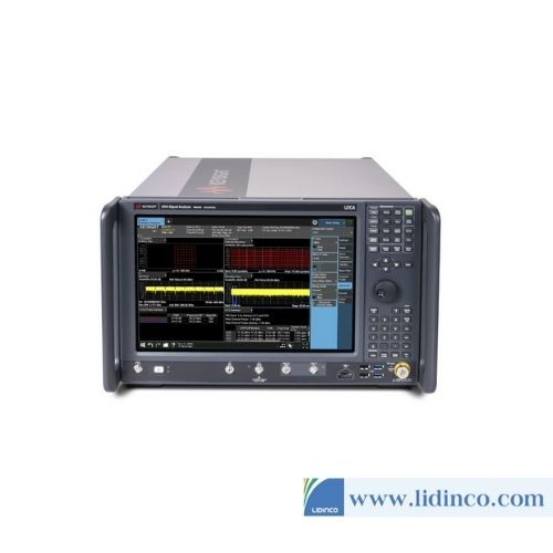
Spectrum Analyzer UXA Keysight N9042B 2Hz-50GHz
Contact
Information
-
Frequency Range:
-
DANL:
-
Phase Noise:
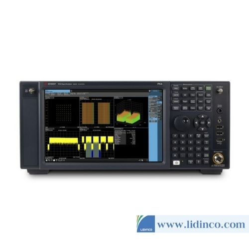
Spectrum Analyzer PXA Keysight N9032B 2Hz-26.5GHz
Contact
Information
-
Frequency:
-
Sampling Rate:
-
Waveform Length:
-
Vertical Resolution:
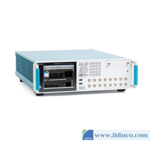
Arbitrary Waveform Generator Tektronix AWG70001B
Contact

Information
-
Frequency:
-
Sampling Rate:
-
Waveform Length:
-
Vertical Resolution:
Arbitrary Waveform Generator Tektronix AWG70002B
Contact

Information
-
Frequency:
-
Sampling Rate:
-
Waveform Length:
-
Vertical Resolution:
Arbitrary Waveform Generator Tektronix AWG5204
Contact
Information
-
Frequency:
-
Sampling Rate:
-
Waveform Length:
-
Vertical Resolution:
Arbitrary Waveform Generator Tektronix AWG5208
Contact

Information
-
Frequency:
-
Sampling Rate:
-
Waveform Length:
-
Vertical Resolution:
Arbitrary Waveform Generator Tektronix AWG5202
Contact

Information
-
Frequency:
-
Sampling Rate:
-
Waveform Length:
-
Vertical Resolution:
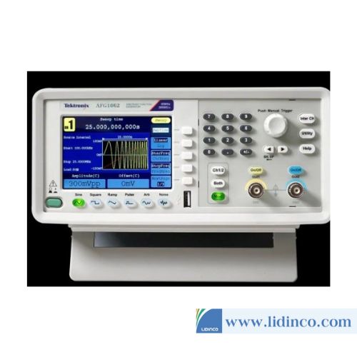
Arbitrary/Function Generator Tektronix AFG1062
Contact
Information
-
Frequency:
-
Sampling Rate:
-
Waveform Length:
-
Vertical Resolution:
Arbitrary/Function Generator Tektronix AFG1022
Contact
Reviews & Comments
Please login to write review!