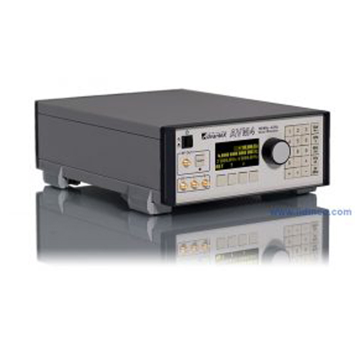
Signal Generator AVM4 100 MHz – 4 GHz
Hotline: +84 906 988 447
Head Office: Ho Chi Minh City
- Tel: +84 2839 778 269 / 3601 6797
- Email: sales@lidinco.com
- Add: 487 Cong Hoa Street, Ward 15, Tan Binh Dist, HCM City, Vietnam
Office: Bac Ninh City
- Tel: +84 222 730 0180
- Email: bn@lidinco.com
- Add: 184 Binh Than Street, Vo Cuong Ward, Bac Ninh City, Vietnam
-
 Technical Counseling
100% Free
Technical Counseling
100% Free
-
 Free Shipping
For 3.000.000vnd Order
Free Shipping
For 3.000.000vnd Order
Data is being updated
Máy phát vector hãng Advantex
Các thông tin chính và thông số kỹ thuật máy phát vector hãng Advantex AVM4 tần số hoạt động từ 100MHz-4GHz
Distinctive Features of AVM4 Vector Modulator
- High output power
- Wide I/Q bandwidth
- Precise output level control
- Output filtering
- Adjustment of LO suppression
- Small size
- Low cost
Brief Description
Advantex AVM4 100 MHz - 4 GHz Quadrature Modulator is is designed to generate a modulated signal at the carrier frequency. It can be applied in testing and debugging of digital communication receivers, as well as for digital modulators which form complex I/Q-signal for later transfer to the carrier frequency.
Figure 1 shows the block diagram of quadrature modulator, the main block of the instrument. Signal from the LO input is fed to the phase-shifter, one output of which is shifted by +45° and multiplied by the signal from the I input, the other shifted by −45°, – multiplied from the Q input. Then these signals are added and fed to the filter block, which suppress the LO products, i.e. 2fLO, 3fLO, etc. The resulting signal is fed to the APC (Automatic Power Control) block, then – to the RF Out output.
The instrument has USB and RS-232 interfaces for SCPI remote control and firmware updating capability.
Key Features of AVM4 RF Vector Modulator
- Output frequency range: 100 MHz – 4 GHz
- I/Q bandwidth: DC - 500 MHz
- I/Q input level (typ.): 0.8 Vpp @ 50Ω
- I/Q sideband suppression (calibrated): −40..−60 dB
- Output P1dB: +20 dBm
- Output level range: −30..+20 dBm
- Absolute level accuracy (typ.): ±0.2 dB
- Output level resolution: 0.05 dB
- Output IP3: +27 dBm
- Noise floor: −120 dBm/Hz @ POUT=0 dBm
- Input LO level: −10..+10 dBm
- LO suppression (calibrated): −60 dBm
- Remote control: RS-232, USB
- Command set: SCPI
- Dimensions: H x W x D: 2U x 42HP(½ 19”) x 315 mm
Applications of Advantex AVM4 I/Q-Modulator
Figure 2 shows an example of instrument application. Signal generator with required carrier frequency is connected to the LO input. Base-band generator outputs or two channels of AWG (Arbitrary Waveform) generator are fed to I and Q inputs. Signal from RF Out is fed to the receiver under test.
Test & Measurement Automation
External control interfaces (RS-232, USB) combined withSCPI protocol allow to use low-cost RF signal generator in ATE applications in volume production as well as in education laboratories where equipment is usually combined to one complex controlled by PC.
| Parameter | Conditions | min. | typ. | max. | Unit |
|---|---|---|---|---|---|
| Frequency bandwidth | −3 dB cutoff | 40 | 4400 | MHz | |
| Level range | −30 | +20 | dBm | ||
| Level resolution | 0.05 | dB | |||
| Absolute level accuracy | −10≤POUT≤+10 dBm | ±0.1 | ±0.3 | dB | |
| within calibration area | ±0.2 | ±0.5 | |||
| Temperature effect | 0.01 | dB/°C | |||
| Calibration area | high bound | +13 | +18 | dBm | |
| low bound | −20 | −15 | |||
| Output P1dB | 2 GHz | +18 | +20 | dBm | |
| Output IP3 | 100 MHz to 4 GHz | +27 | dBm | ||
| VSWR (RF Out @ 50Ω load) | 1.9 | ||||
| Level settling time | 100 | ms | |||
| RF Out ON/OFF switching time | from edge of triggering signal | 0.1 | ms | ||
| Noise floor | 100 MHz | −117 | dBm/Hz | ||
| 1 GHz | −124 | ||||
| 4 GHz | −128 | ||||
| 2-nd harmonics & LO products @ POUT=0 dBm | 100 MHz | −31 | dB | ||
| 1 GHz | −44 | ||||
| 4 GHz | −44 | ||||
| 3-rd harmonics & LO products @ POUT=0 dBm | 100 MHz | −43 | dB | ||
| 1 GHz | −66 | ||||
| 4 GHz | −85 | ||||
| Acceptable DC voltage at RF Out | 0 | 8 | V | ||
| RF Out level @ OFF state | −40 | −60 | dBm |
 Actual signal level vs. frequency at various levels set to the instrument Actual signal level vs. frequency at various levels set to the instrument |  Absolute level accuracy Absolute level accuracy |
LO Input Specifications of Advantex AVM4 I/Q-Modulator
| Parameter | Conditions | min. | typ. | max. | Unit |
|---|---|---|---|---|---|
| Frequency range | 100 | 4000 | MHz | ||
| VSWR (LO input @ 50Ω) | 500 MHz to 4 GHz | 1.5 | |||
| 100 MHz to 500 MHz | 3 | ||||
| LO input level | −10 | +10 | dBm | ||
| LO to RF Out suppression | uncalibrated (@ PLO=0 dBm) | −60 | −40 | −25 | dB |
| calibrated | −60 |
 LO suppression and RF Out level at OFF state LO suppression and RF Out level at OFF state |
I/Q Input Specifications of Advantex AVM4 Vector Modulator
| Parameter | Conditions | min. | typ. | max. | Unit |
|---|---|---|---|---|---|
| Frequency bandwidth | may be reduced by output filter | DC | 500 | MHz | |
| VSWR (I/Q inputs @ 50Ω) | @ 100 MHz | 1.1 | |||
| Flatness | DC to 100 MHz, FLO>500 MHz | 1.5 | dBpp | ||
| full I/Q BW | 6 | ||||
| Sideband suppression | uncalibrated (@ PLO=0 dBm) | −60 | −40 | −20 | dB |
| calibrated | −60 | ||||
| I/Q inputs two-tone IMD3 @ VIQ=0.8 Vpp | fIQ=200 MHz | −40 | dB | ||
| I/Q input level | @ 50Ω load | 0.8 | 1.6 | Vpp | |
| I/Q gain imbalance | 0.02 | dB |
 Sideband suppression @ PLO = −10 .. + 12 dBm Sideband suppression @ PLO = −10 .. + 12 dBm |  Sideband suppression @ PLO = −10 .. + 12 dBm (contour graph) Sideband suppression @ PLO = −10 .. + 12 dBm (contour graph) |
Accessories
-
Voltage Range:
-
Current Range:
-
Display Resolution:
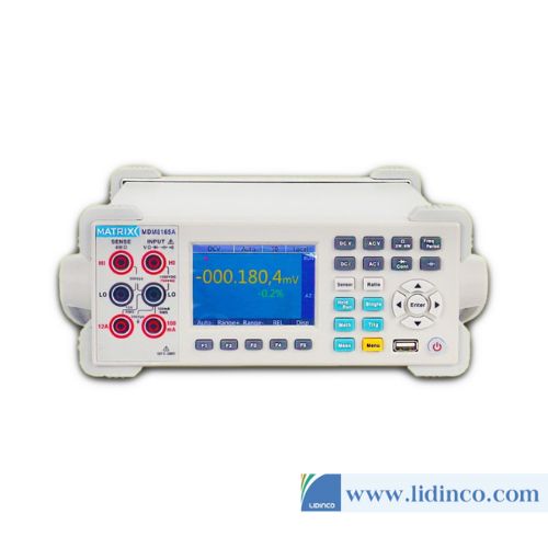
Digital Multimeter Matrix MDM-8165A
-
Voltage Range:
-
Current Range:
-
Display Resolution:
Digital Multimeter Matrix MDM-8165
Please login to write review!