Máy hiện sóng, Oscilloscope LeCroy DDA 735Zi-A 3.5 GHz, 4 CH
Máy hiện sóng, Oscilloscope LeCroy DDA 735Zi-A 3.5 GHz, 4 CH
- Vui lòng liên hệ để kiểm tra tình trạng kho
- Tạm thời chưa có khuyến mãi cho sản phẩm này
Hotline: 0906.988.447
Liên hệ: Hồ Chí Minh
- Điện thoại: (028).3977.8269
- Email: sales@lidinco.com
- Địa chỉ: 487 Cộng Hòa, Phường 15, Quận Tân Bình, TP. HCM
Liên hệ: Bắc Ninh, Hà Nội
- Điện thoại: (0222).730.0180
- Email: bn@lidinco.com
- Địa chỉ: 184 Bình Than, Phường Võ Cường, TP. Bắc Ninh
-
 Tư vấn kĩ thuật
Miễn phí
Tư vấn kĩ thuật
Miễn phí
-
 Miễn phí vận chuyển
Đơn hàng trên 3 triệu
Miễn phí vận chuyển
Đơn hàng trên 3 triệu
Dữ liệu đang được cập nhật
Giới thiệu
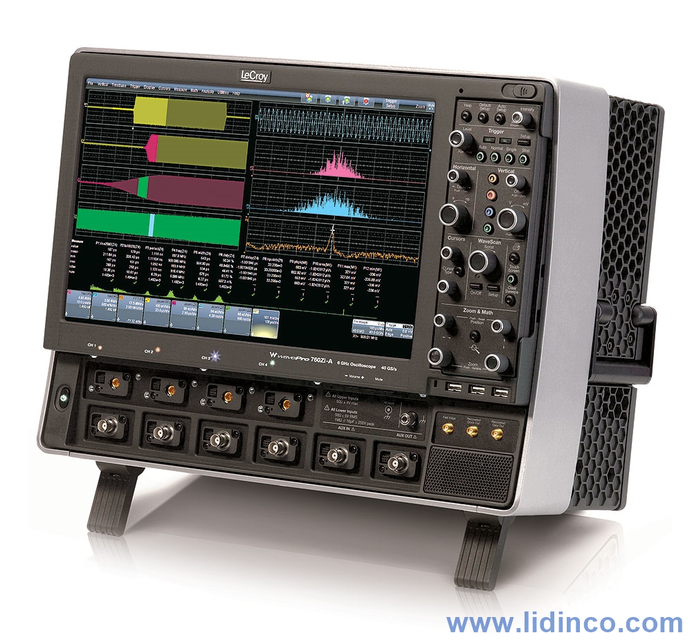
Máy hiện sóng LeCroy DDA735Zi-A băng thông 3.5 GHz, lấy mẫu 20 GSa/s, 4 kênh, bộ nhớ 32 Mpts/kênh, màn hình 15.4 inch.

Teledyne LeCroy Disk Drive Analyzers (DDA) assist data storage design engineers by integrating tools that improve the time to market of new products and accelerate understanding and failure analysis on existing drives. Teledyne LeCroy continues that tradition with the DDA 7 Zi-A Series equipped with its powerful Disk Drive Analysis toolset. Capture, view, and analyze the wave shape of high-speed, complex drive signals with speed and integrity. Data Storage applications are memory intensive as capturing multiple sectors or a complete track of data can be important in troubleshooting a design or characterizing media.
The X-Stream II architecture enables fast and accurate measurements and analysis of disk drive signals. Memory can be extended to 128 Mpts/Ch (256 Mpts/Ch on 2 Ch) using Option L. Both the DDA 760Zi and DDA 735Zi offer the convenience of selectable 50 Ω or 1 MΩ inputs. The standard 20 Mpts of waveform memory and 40 GS/s capture on two channels, means multiple drive sectors can be acquired at once.
Acquire a head signal up to 6 GHz, and then QuickZoom it from the front panel. The DDA copies and expands the drive signal automatically. Simply scroll horizontally and vertically to examine any sector. Multiple zooms let you view up to eight separate areas of the head signal; each zoom comes in a distinct color. Disk drive parameters let you characterize the pulse width variation or signal-to-noise ratio across a region. Failure Analysis engineers can store and recall golden waveforms and panel setups to compare problem drives with the known good drives. Analog-to-digital converters running at speeds up to 40 GS/s ensure the right sensitivity to measure today's high-speed read channels. In every DDA, you can run your customer-developed scripts to view the captured signal with the filters matched to your channel and media. Custom user scripts can be created in MATLAB, Visual Basic, Excel or other formats.
The DDA's disk triggers allow you to set up a series of events in the signal that then cause a trigger. For example, qualify the signal on the index signal and then capture all the sectors of information on the track. As memory is increased in the DDA, more sectors can be captured, with up to 50 picosecond/sample time resolution. Up to 15,000 sectors of data can be gathered with the DDA 7 Zi-A analyzers. An optional capability, Streaming Sequence, uses the X-Stream II and the fast hardware architecture of the DDA to streamup to 300,000 segments of data to memory; all taken at a high trigger rate.
One press on the DDA menu takes you directly to the Disk Drive Analyzer features. The familiar controls on the front panel, coupled with a natural, context-sensitive graphical user-interface, react quickly to your commands. Functionality is exactly where you expect it to be. The DDA 7 Zi-A provides one button access to all the tools needed to accurately debug and analyze disk drive operation.
The DDA 7 Zi-A features:
- 31 custom parameters
- 4 specific drive trigger
- Sector
- Servo Gate
- PES trigger
- Read Gate Trigger
- Advanced drive analysis tools
Advanced Disk Drive analysis tools capabilities include:
- Head Filter Equalizer emulation
- Channel Emulation
- SAM Histograms
- Plot of SAM values
- PES runout analysis
- Analog Compare
Simultaneously connecting low-speed signals, like index and servo gate, and high-speed signals, like read channels has never been easier. With integrated 50 Ω and 1 MΩ inputs on all models, there is no longer a need for expensive adapters.
Vertical System | |
| Analog Bandwidth (Max) | 3.5 GHz |
| Analog Bandwidth @ 50 Ω (-3 dB) (ProBus Input) | 3.5 GHz (≥10 mV/div) |
| Analog Bandwidth @ 1 MΩ (-3 dB) (ProBus Input) | 500 MHz (typical) (≥5 mV/div) |
| Rise Time (10-90%, 50 Ω) | 120ps (typical, flatness mode) |
| Rise Time (20-80%, 50 Ω) | 90ps (typical, flatness mode) |
| Input Channels | 4 |
| Bandwidth Limiters | 20 MHz, 200 MHz, 1 GHz, 3 GHz |
| Input Impedance | 50 Ω+/-2% or 1 MΩ||16pF, 10 MΩ || 11 pF with supplied Probe |
| Input Coupling | ProBus Inputs - 1 MΩ: AC, DC, GND; 50 Ω: DC, GND |
| Maximum Input Voltage | 50 Ω: ±5 Vrms 1 MΩ: 250 V max. (peak AC: < 10 kHz + DC) |
| Channel-Channel Isolation | DC to 2 GHz: 46 dB (>200:1) 2 to 4 GHz: 34 dB (>50:1) 4 to 6 GHz: 26 dB (>20:1) (For any two ProLink input channels, same v/div settings, typical) |
| Vertical Resolution | 8 bits; up to 11 bits with enhanced resolution (ERES) |
| Sensitivity | 50 Ω: 2 mV-1 V/div, fully variable (2-9.99 mV/div via zoom); 1 MΩ: 1 mV-10 V/div, fully variable |
| DC Vertical Gain Accuracy (Gain Component of DC Accuracy) | ±1% F.S. (typical), offset at 0V; ±1.5% F.S. (test limit), offset at 0V |
| Vertical Noise Floor (50 mV/div) | 1.30 mVrms (typical) |
| Offset Range | 50 Ω (ProBus) ±750 mV @ 10 mV - 170 mV/div ±4 V @ 172 mV - 1 V/div1 MΩ ±1 V @ 2 mV - 128 mV/div ±10 V @ 130 mV - 1.28 V/div ±100 V @ 1.3 V - 10 V/div |
| DC Vertical Offset Accuracy | ±(1.5% of offset setting + 1.5% F.S. + 1 mV) (typical) ±(1.5% of offset setting + 2.5% F.S. + 2 mV) (test limit) |
Horizontal System | |
| Timebases | Internal timebase common to 4 input channels; an external clock may be applied at the auxiliary input |
| Time/Division Range | 20 ps/div-3200 s/div (Real-Time Mode: 20 ps/div - 2000 s/div; RIS mode: 20 ps/div - 10 ns/div, user selectable at ≤10ns/div; Roll mode: 100 ms/div up to 3200 s/div, user selectable at ≥100 ms/div and ≤5 MS/s), depending on memory length |
| Clock Accuracy | < 1 ppm + (aging of 0.5ppm/yr from last calibration) |
| Sample Clock Jitter | up to 10µs Acquired Time Range: 100fsrms (Internal Timebase Reference)up to 3.2ms Acquired Time Range: 150fsrms (Internal Timebase Reference) |
| Delta Time Measurement Accuracy | √2*√((Noise/SlewRate)^2+(Sample Clock Jitter)^2 ) (RMS)+(clock accuracy*reading)(seconds) |
| Jitter Measurement Floor | √((Noise/SlewRate)^2+(Sample Clock Jitter)^2 ) secondsrms (TIE) |
| Jitter Noise Floor | 800 fs (TIE, typical) |
| Jitter Between Channels | <560fsrms (TIE, typical, measured at maximum bandwidth) |
| Trigger and Interpolator Jitter | ≤ 2 ps RMS (typical) <0.1 ps RMS (typical, software assisted) |
| Channel-Channel Deskew Range | ±9 x time/div. setting, 100 ms max., each channel |
| External Timebase Reference (Input) | 10 MHz; 50 Ω impedance, applied at the rear input |
| External Timebase Reference (Output) | 10 MHz; 50 Ω impedance, output at the rear |
| External Clock | 30 MHz-2 GHz, 50 Ω impedance, applied at the auxiliary input |
Acquisition System | |
| Single-Shot Sample Rate/Ch | 40 GS/s on 2 Ch 20 GS/s on 4 Ch |
| Random Interleaved Sampling (RIS) | 200 GS/s for repetitive signals (20 ps/div to 10 ns/div) |
| Maximum Trigger Rate | 1,000,000 waveforms/second (in Sequence Mode, up to 4 channels) |
| Standard Memory (4 Ch / 2 Ch / 1Ch) (Number of Segments) | 32M / 64M / 64M (15,000) |
| Memory Options (4 Ch / 2 Ch / 1Ch) (Number of Segments) | M-64 Option: 64M / 128M / 128M (15,000) L-128 Option: 128M / 256M / 256M (15,000) |
Acquisition Processing | |
| Averaging | Summed averaging to 1 million sweeps; continuous averaging to 1 million sweeps |
| Enhanced Resolution (ERES) | From 8.5 to 11 bits vertical resolution |
| Envelope (Extrema) | Envelope, floor, or roof for up to 1 million sweeps |
| Interpolation | Linear or Sin x/x |
Triggering System | |
| Modes | Normal, Auto, Single, and Stop |
| Sources | Any input channel, Aux, Aux/10, or line; slope and level unique to each source (except line trigger) |
| Coupling Mode | DC, AC, HFRej, LFRej |
| Pre-trigger Delay | 0-100% of memory size (adjustable in 1% increments of 100 ns) |
| Post-trigger Delay | 0-10,000 divisions in real time mode, limited at slower time/div settings or in roll mode |
| Hold-off by Time or Events | From 2 ns up to 20 s or from 1 to 99,999,999 events |
| Internal Trigger Range | ±4.1 div from center (typical) |
| Trigger Sensitivity with Edge Trigger ProBus Inputs | 2 div @ < 3.5 GHz 1.5 div @ < 1.75 GHz 1.0 div @ < 200 MHz (for DC, AC, LFRej coupling, ≥ 10 mV/div, 50 Ω ) |
| External Trigger Sensitivity, (Edge Trigger) | 2 div @ < 1 GHz 1.5 div @ < 500 MHz 1.0 div @ < 200 MHz (for DC, AC, LFRej coupling) |
| Max. Trigger Frequency, SMART Trigger | 2.0 GHz @ ≥ 10 mV/div (minimum triggerable width 250 ps) |
| External Trigger Input Range | Aux (±0.4 V); Aux/10 (±4 V) |
Basic Triggers | |
| Edge | Triggers when signal meets slope (positive, negative, or either) and level condition. |
| Window | Triggers when signal exits a window defined by adjustable thresholds |
| TV-Composite Video | Triggers NTSC or PAL with selectable line and field; HDTV (720p, 1080i, 1080p) with selectable frame rate (50 or 60 Hz) and Line; or CUSTOM with selectable Fields (1-8), Lines (up to 2000), Frame Rates (25, 30, 50, or 60 Hz), Interlacing (1:1, 2:1, 4:1, 8:1), or Synch Pulse Slope (Positive or Negative). |
SMART Triggers | |
| State or Edge Qualified | Triggers on any input source only if a defined state or edge occurred on another input source. Delay between sources is selectable by time or events. |
| Qualified First | In Sequence acquisition mode, triggers repeatably on event B only if a defined pattern, state, or edge (event A) is satisfied in the first segment of the acquisition. Holdoff between sources is selectable by time or events. |
| Dropout | Triggers if signal drops out for longer than selected time between 1 ns and 20 s. |
| Pattern | Logic combination (AND, NAND, OR, NOR) of 5 inputs (4 channels and external trigger input). Each source can be high, low, or don't care. The High and Low level can be selected independently. Triggers at start or end of the pattern. |
SMART Triggers with Exclusion Technology | |
| Glitch | Triggers on positive or negative glitches with widths selectable as low as 500ps (depending on oscilloscope bandwidth) to 20 s, or on intermittent faults. |
| Width (Signal or Pattern) | Triggers on positive, negative, or both widths with widths selectable as low as 500ps (depending on oscilloscope bandwidth) to 20 s, or on intermittent faults. |
| Interval (Signal or Pattern) | Triggers on intervals selectable between 1 ns and 20 s. |
| Timeout (State/Edge Qualified) | Triggers on any source if a given state (or transition edge) has occurred on another source. Delay between sources is 1 ns to 20 s, or 1 to 99,999,999 events. |
| Runt | Trigger on positive or negative runts defined by two voltage limits and two time limits. Select between 1 ns and 20 ns. |
| Slew Rate | Trigger on edge rates. Select limits for dV, dt, and slope. Select edge limits between 1 ns and 20 ns. |
| Exclusion Triggering | Trigger on intermittent faults by specifying the expected behavior and triggering when that condition is not met |
Cascade (Sequence) Triggering | |
| Capability | Arm on "A" event, then Trigger on "B" event. Or Arm on "A" event, then Qualify on "B" event, and Trigger on "C" event. |
| Types | Cascade A then B: Edge, Window, Pattern (Logic) Width, Glitch, Interval, Dropout, or Measurement. Measurement can be on Stage B only. Cascade A then B then C (Measurement): Edge, Window, Pattern (Logic), Width, Glitch, Interval, Dropout, or Measurement. Measurement can be on Stage C only. Cascade A then B then C: Edge, Window, Pattern (Logic) |
| Holdoff | Holdoff between A and B or B and C is selectable by time (1ns to 20s) or number of events. Measurement trigger selection as the last stage in a Cascade precludes a holdoff setting between the prior stage and the last stage. |
High Speed Serial Protocol Triggering | |
| Data Rates | (Option WPZi-MSPT) 100 Mb/s - 1.25 Gb/s |
| Pattern Length | 80 bits, NRZ or 8b10b |
| Clock and Data Outputs | 400mVp-p (typical) AC coupled |
| Clock Recovery Jitter | 2 ps rms + 0.3% Unit Interval rms for PRBS data patterns with 50% transition density |
| Hardware Clock Recovery Loop BW | PLL Loop BW = Fbaud/5500, 100 Mb/s to 2.488 Gb/s (typical) |
Low Speed Serial Protocol Triggering (Optional) | |
| Optionally available | I2C, SPI (SPI, SSPI, SIOP), UART-RS232, CAN, LIN, FlexRay, MIL-STD-1553, AudioBus |
Measurement Trigger | |
| Measurement Trigger Capability | Select from a large number of measurement parameters trigger on a measurement value with qualified limits. Can be used as only trigger or last event in a Cascade Trigger. |
Color Waveform Display | |
| Type | Color 15.3" flat panel TFT-Active Matrix LCD with high resolution touch screen |
| Resolution | WXGA; 1280 x 768 pixels. |
| Number of traces | Display a maximum of 16 traces (up to 40 with some software options). Simultaneously display channel, zoom, memory and math traces. |
| Grid Styles | Auto, Single, Dual, Quad, Octal, X-Y, Single+X-Y, Dual+X-Y |
| Waveform Representation | Sample dots joined, or sample dots only |
Internal Waveform Memory | |
| Internal Waveform Memory | 12 active waveform memory traces (M1-M12) store 16 bit/point full length waveforms. Waveforms can be stored to any number of files limited only by the data storage media capacity. |
Integrated Second Display | |
| Type | Supports touch screen integration of user-supplied second display with split-grid capability. (Note: touch screen driver for second display may not be a Fujitsu driver) |
| Resolution | Determined by display chosen by user |
LeCroy WaveStream™ Fast Viewing Mode | |
| Intensity | 256 Intensity Levels, 1-100% adjustable via front panel control |
| Number of Channels | up to 4 simultaneously |
| Max Sampling Rate | 40 GS/s |
| Waveforms/second (continuous) | up to 2500 Waveforms/second |
| Operation | Front panel toggle between WaveStream ON (Analog), ON (Color) and OFF |
Analog Persistence Display | |
| Analog and Color-Graded Persistence | Variable saturation levels; stores each trace's persistence data in memory |
| Persistence Types | Select analog, color, or three-dimensional |
| Trace Selection | Activate persistence on all or any combination of traces |
| Persistence Aging | Select from 500 ms to infinity |
| Sweep Display Modes | All accumulated, or all accumulated with last trace highlighted |
High Speed Digitizer Output (Option) | |
| Type | LeCroy LSIB |
| Transfer Rate | up to 325 Mpt/s (Maximum) |
| Output Protocol | PCI Express, Gen 1 (4 lanes utilized for data transfer) |
| Control Protocol | TCP/IP |
| Command Set | Via Windows Automation, or via LeCroy Remote Command Set |
Processor/CPU | |
| Type | Intel® CoreTM i7-2600 Quad, 2.6 GHz (up to 3.8 GHz in Turbo mode) (or better) |
| Processor Memory | 8 GB standard for STD memory (32 Mpt) and M-64 memory options 16 GB standard for L-128 memory options Up to 32 GB optional |
| Operating System | Microsoft Windows® 7 Professional Edition (64-bit) |
| Real Time Clock | Date and time displayed with waveform in hardcopy files. SNTP support to synchronize to precision internal clocks. |
Zoom Expansion Traces | |
| Zoom Expansion Traces | Display up to 12 Zoom and 12 Math/Zoom traces |
Setup Storage | |
| Front Panel and Instrument Status | Store to the internal hard drive, over the network, or to a USB-connected peripheral device. |
Interface | |
| Remote Control | Via Windows Automation, or via LeCroy Remote Command Set |
| Network Communication Standard | VXI-11 or VICP, LXI Class C (v 1.2) Compliant |
| GPIB Port | Supports IEEE - 488.2 |
| LSIB Port (optional) | Supports PCIe Gen1 x4 protocol with LeCroy supplied API |
| Ethernet Port | Supports 10/100/1000BaseT Ethernet interface (RJ45 port) |
| USB Ports | minimum 6 total (incl. 3 front panel) USB 2.0 ports support Windows compatible devices |
| External Monitor Port | 15 pin D-Type WXGA compatible to support customer-supplied external monitor. Includes support for extended desktop operation with second monitor. |
| Peripheral Bus | LeCroy LBUS standard |
Auxiliary Input | |
| Signal Types | For External Trigger Input |
| Coupling | 50 Ω: DC; 1 MΩ: AC, DC, GND |
| Max. Input Voltage | 50 Ω: 5 Vrms; 1 MΩ: 250 V (Peak AC < 10 kHz + DC) |
Auxiliary Output | |
| Signal Types | Select from calibrator, control signals or Off |
| Output Signal | 500 Hz-5 MHz square wave or DC level; 2.5mV to 500 mV into 50 Ω (5 mV-1 V into 1 MΩ) |
| Control Signals | Trigger enabled, trigger out, pass/fail status, off |
| Connector Type | BNC, located on front |
Automatic Setup | |
| Auto Setup | Automatically sets timebase, trigger, and sensitivity to display a wide range of repetitive signals |
| Find Vertical Scale | Automatically sets the vertical sensitivity and offset for the selected channel to display a waveform with the maximum dynamic range |
General | |
| Auto Calibration | Ensures specified DC and timing accuracy is maintained for 1 year minimum. |
Probes | |
| Probes | Qty. (4) ÷10 Passive Probes |
| Probe System | Probus (and ProLink on 4-6 GHz models). Automatically detects and supports a variety of compatible probes |
| Scale Factors | Automatically or manually selected depending on probe used |
| Calibration Output | Cal Output: 1kHz square wave, 1Vp-p (typical), output to probe hook. Fast Edge Output: 5MHz square wave, 450mVp-p (typical), 110ps rise time, output to SMA connector, AC Coupled. |
Power Requirements | |
| Voltage | 100-240 VAC ±10% at 45-66 Hz; 100-120 VAC ±10% at 380-420 Hz; Automatic AC Voltage Selection; Installation Category 300 V CAT II |
| Max. Power Consumption | 800 W/800 VA |
Environmental and Safety | |
| Temperature (Operating) | +5 °C to +40 °C including CD-RW/DVD-ROM drive |
| Temperature (Non-Operating) | -20 °C to +60 °C |
| Humidity (Operating) | 5% to 80% relative humidity (non-condensing) up to +31 °C. Upper limit derates to 50% relative humidity (non-condensing) at +40 °C. |
| Humidity (Non-Operating) | 5% to 95% relative humidity (non-condensing) as tested per MIL-PRF-28800F |
| Altitude (Operating) | Up to 10,000 ft. (3048 m) at or below +25 °C |
| Altitude (Non-Operating) | Up to 40,000 ft. (12,192 m) |
| Random Vibration (Operating) | 0.5 grms 5 Hz to 500 Hz, 10 minutes in each of three orthogonal axes, 30 minutes total |
| Random Vibration (Non-Operating) | 2.0 grms 5 Hz to 500 Hz, 10 minutes in each of three orthogonal axes, 30 minutes total |
| Functional Shock | 20 g peak, half sine, 11 ms pulse, 3 shocks (positive and negative) in each of three orthogonal axes, 18 shocks total |
Physical Dimensions | |
| Dimensions (HWD) | 14"H x 18.4"W x 11.4"D (355 x 467 x 289 mm) |
| Weight | 40.5 lbs. (18.4 kg) |
| Shipping Weight | 62 lbs. (28.2 kg) |
Phụ kiện
-
Dải đo điện áp:
-
Dải đo dòng điện:
-
Chữ số hiển thị:
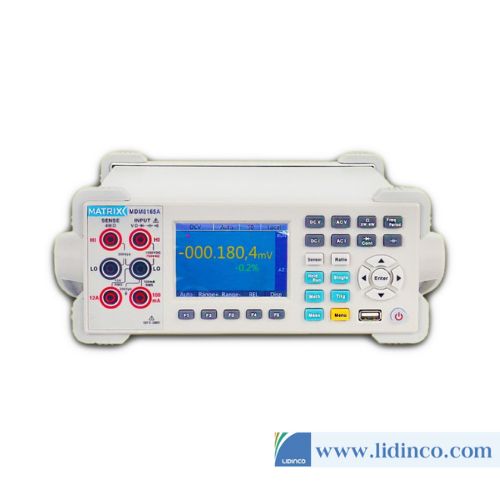
Đồng hồ vạn năng để bàn độ chính xác cao Matrix MDM-8165A
-
Dải đo điện áp:
-
Dải đo dòng điện:
-
Chữ số hiển thị:
Đồng hồ vạn năng để bàn độ chính xác cao Matrix MDM-8165
-
Số cửa:
-
Dung tích chứa:
-
Chọn thuộc tính:
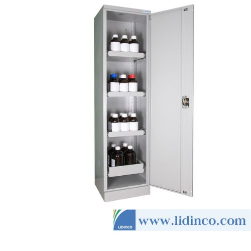
Tủ thép chống cháy nổ 1 cửa Ecosafe ALT115

-
Tần số phát xung:
-
Tốc độ lấy mẫu:
-
Chiều dài sóng:
-
Độ phân giải dọc:
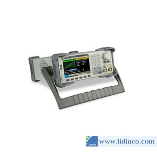
Máy phát xung Lecroy T3AFG500

-
Tần số phát xung:
-
Tốc độ lấy mẫu:
-
Chiều dài sóng:
-
Độ phân giải dọc:
Máy phát xung Lecroy T3AFG350

-
Tần số phát xung:
-
Tốc độ lấy mẫu:
-
Chiều dài sóng:
-
Độ phân giải dọc:
Máy phát xung Lecroy T3AFG200

-
Tần số phát xung:
-
Tốc độ lấy mẫu:
-
Chiều dài sóng:
-
Độ phân giải dọc:
Máy phát xung Lecroy T3AFG120

-
Tần số phát xung:
-
Tốc độ lấy mẫu:
-
Chiều dài sóng:
-
Độ phân giải dọc:
Máy phát xung Lecroy T3AFG80

-
Tần số phát xung:
-
Tốc độ lấy mẫu:
-
Chiều dài sóng:
-
Độ phân giải dọc:
Máy phát xung Lecroy T3AFG60

-
Tần số phát xung:
-
Tốc độ lấy mẫu:
-
Chiều dài sóng:
-
Độ phân giải dọc:
Máy phát xung Lecroy T3AFG30
-
Tần số phát xung:
-
Tốc độ lấy mẫu:
-
Chiều dài sóng:
-
Độ phân giải dọc:
Máy phát xung Lecroy T3AFG40
Vui lòng đăng nhập để viết đánh giá!